
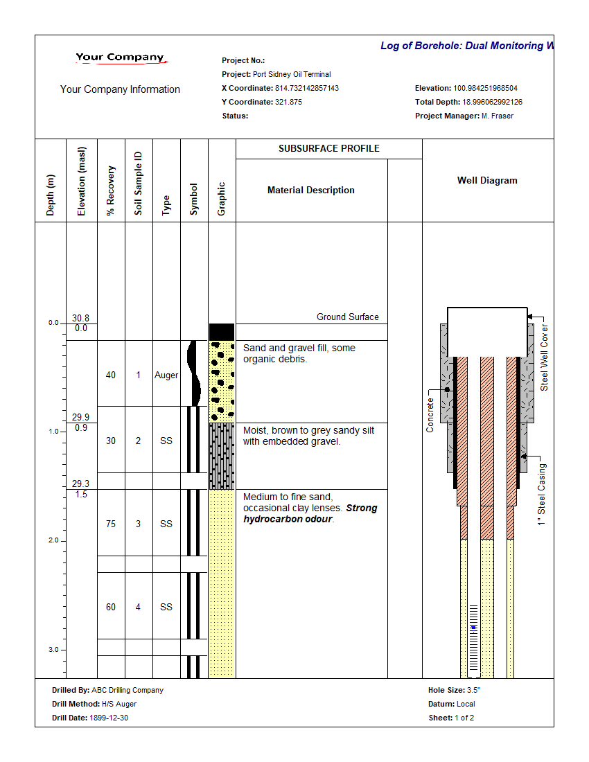
WinLoG can display a wide variety of well diagrams at varying levels of detail and complexity. Monitoring, extraction, injection, and almost any other type of well can be displayed on the log. Well completion details and data can be displayed graphically in one or more columns of the log. Almost all of the well information is drawn to scale; including casings, screens, covers, caps, and miscellaneous fittings.
The data for each well column is grouped into datasets and stored according to the name of the well column. This allows for the display of more than one set of well data on a log.
When a new log is created, well datasets will be automatically created for whatever well columns are specified in the template. The names of these well datasets will appear in the Well Data submenu of the Edit menu and Popup menu.
The data for a well consists of:
- hole diameter and layout,
- well components,
- water level measurements,
- and annotation.
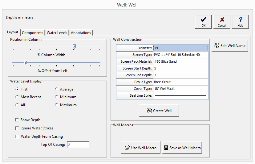
To create or edit a well diagram either click on the well on the log or select Edit > Well Data > Well Name. The well diagram form has four tabs; one for the layout, one for the components, one for the water levels, and one for the annotation.
There are three ways to create a well diagram:
- Specify the well construction information.
- Use a Well Macro.
- Specify the well components, water levels, and annotation.
Specify the Well Construction Information
The components and annotation can be automatically created by the program using the information specified for the well construction.
Diameter: This is the outside diameter of the well.
Screen Type: This is used to select the type and diameter of the screen.
Screen Pack Material: This is used to select the packing material around the screen.
Screen Start Depth: This is used to specify the start depth of the screen.
Screen End Depth: This is used to specify the end depth of the screen.
Grout Type: This is used to select the type of grout used in the well.
Cover Type: This is used to select the type and height of the well cover.
Seal Line Style: This is used to select the line style for the seal.
After this information has been specified click on the Create Well button to automatically generate the components and annotation for the well. The layout, components, water levels, and annotation can then be edited as described in the sections below.
Use a Well Macro
A well macro contains previously saved information for the layout, components, water levels, and annotation for a well diagram. If a well macro is to be used it should be selected first by pressing the Use Well Macro button on the Layout tab. Well macros can also be created after the well data has been input for a log, using the Save as Well Macro button on the Layout tab.
When this button is pressed a form will be displayed where you can specify the name of the well macro. The information from the well macro will then be used for the well diagram.
Specify the well components, water levels, and annotation
A well diagram can be created by specifying all of the components, water levels, and annotation individually. This would be the most time consuming method.
Editing a Well Diagram
No matter how the well diagram was created, it can be edited on the four Well Diagram form tabs as described below.
Layout

The layout tab is used to control the position of the well diagram in the column and types of water levels to display. The following information can be edited using the Layout tab:
% Column Width: This is the percentage of the width of the column to use for the hole. The horizontal scale of the well column will then be set such that the hole diameter specified above is equal to this percentage of column width. When setting the % of Column Width space should be made on the sides of the hole for annotation.
% Offset Left: This is the percentage of the column width to offset the hole from the left side of the column. This parameter is used to position the hole inside the column. The sum of the % Offset and % of Column Width should always be less than or equal to 100. For example, if the % of Column Width is 70 and the % Offset is 10. Then the leftmost 10% of the column would be used for annotation, the next 70% of the column would contain the well components, and the last 20% of the column would be used for annotation.
Water Level Display Type: This is used to select the type of water levels to display when there are multiple water levels.
Show Depth: This will automatically annotate the water depth on the log.
Ignore Water Strikes: When there are multiple water levels, check this box to not include water strikes.
Water Depth from Casing: Check this box to indicate that the water depths are measured from the top of the casing.
Components
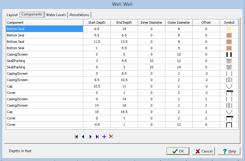
The Components tab is used to enter the well components. These components consist of covers, caps, casings/screens, seals/packing, bottom seals, joints, and miscellaneous fittings.
The following information can be edited using this tab:
Component: This is the type of well component. When the cursor is clicked in this column, a combo box will be displayed. By clicking on the arrow to the right of this box, the type of component can be selected. The types of components that can be selected are Cover, Cap, Joint/Misc., Casing/Screen, Seal/Packing, and Bottom Seal.
Start Depth: This is the start depth of the component in the same units as set in the template.
End Depth: This is the end depth of the component
Inner Diameter: This is the inner diameter of the component. It is only used for Seal and some Casing/Misc. components. These components will be drawn such that the shading and symbol patterns will fill the gap between the inner and outer diameters of the component. The components that use the inner diameter are discussed under the appropriate symbol at the end of this section.
Outer Diameter: This is the outer diameter of the component and is used by all of the types of components. The outer diameter must be less than the hole diameter. The width of the component inside the well column is determined by the ratio of the outer diameter and hole diameter. For example; if the outer diameter is 2 inches and the hole diameter is 8 inches, then the components width would be ¼ of the hole width.
Offset: This is the offset of the component from the center of the hole. Offsets to the left are negative and offsets to the right are positive. By specifying an offset to the component, multiple casings and piezometers can be placed within a single well column. For example; to specify two piezometers in a hole 10 inches in diameter. One piezometer could have an offset of –3 inches and the other piezometer could have an offset of 3 inches. The first piezometer would then be between 2 and 4 inches on the left side of the hole, and the second piezometer would be between 2 and 4 inches on the right side of the hole.
Symbol: This is the symbol to use for the component. The symbols available will vary depending upon the type of component. When the cursor is clicked inside this column one of the symbol forms described below will be displayed, depending on the type of component.
Water Levels
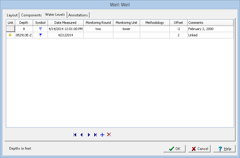
One or more water levels can be displayed on the well diagram. The following information can be edited using this tab:
Link: To link a water level to an EDMS groundwater sample click on the Link column for that water level. Then click on the button that appears. A list of EDMS groundwater samples that are associated with the boring/well will be displayed, select the groundwater sample to link. The data from the EDMS groundwater sample will automatically be shown on the Water Levels tab and well column. In the Link column for this water level a triangle symbol will be shown to indicate that the water level is linked to an EDMS groundwater sample. Except for the symbol and comments, the data for this linked water level cannot be edited in the boring/well log.
Depth: This is the measured depth of the water level in the same units as set in the template.
Symbol: This is the symbol to use to represent the water table. When the cursor is clicked on this column, the Water Level Symbol form is displayed. This form is used to select the symbol, symbol size, color, and line width.
Date Measured: This can be used to select the date that the water level was measured.
Monitoring Round: This is used to specify the monitoring round for the water level.
Monitoring Unit: This is used to specify the monitoring unit for the water level.
Methodology: This is used to specify the methodology used to measure the water level.
Offset: This is the offset to place the water level symbol from the center of the hole. Offsets to the left are negative and offsets to the right are positive.
Comments: This is the text to display above the water level symbol. The text will be oriented vertically above the symbol.
Annotations
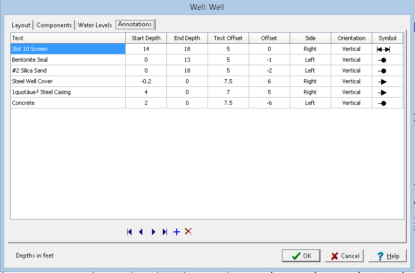
Annotations are used to enter the text describing the well completion details and other information. The following information can be edited using this tab:
Text: This is the text to use for annotation.
Start Depth: This is the starting depth to display the text, the text will be positioned below this start depth. If the start depth is zero and the symbol type is not a double arrow, the start depth will be ignored and the end depth will be used to position the text.
End Depth: This is the end depth to use for displaying the text. The text will be positioned above this depth. If the end depth is zero and the symbol type is not a double arrow, the end depth will be ignored and the start depth will be used to position the text.
Text Offset: This is the offset to place the text from the center of the hole. The sign of the offset is ignored, and the Side is used to determine which side of the hole to place the text. In order for the text to appear outside of the well components, the text offset must be greater than the hole radius.
Offset: This is the offset used to position the start of the arrow or circle inside of the well components. Offsets to the left are negative and offsets to the right are positive. In order for the arrow or circle that leads to the text to start in the well components, the offset must be less than the hole radius.
Side: This is the side of the hole to place the text. When the cursor is clicked inside of this column, a combo box will be displayed, and either the left or right side can be selected.
Orientation: This is the orientation of the text. When the cursor is clicked inside of this column, a combo box will be displayed and the orientation can be set to either horizontal or vertical.
Symbol: This is the symbol to use to draw the text leaders. When the cursor is clicked inside this column, the Annotation Symbol form will be displayed. This form can be used to select the symbol type, symbol size, and line style. If the symbol type is Double Arrow and the text orientation is horizontal, the double arrows will not be drawn.
Transform your logging experience with WinLoG. Say goodbye to complicated tools that overwhelm and frustrate. With WinLoG, create borehole and well logs effortlessly, enhance collaboration, and deliver seamless projects.