
If you are working with borehole data or cross-sections in WinFence, precision is everything. Whether you are defining stratigraphic layers or lens deposits, ensuring that your boundaries align perfectly with your data points is crucial for professional geological reporting.
The number of boundaries a strata has depends on the type of strata. Layers have a top and bottom boundary. Faults, lenses, alteration zones and intrusions have only one boundary. These boundaries can be defined by a series of points on the cross-section, or by the boundaries of other strata.
Cross-section Strata
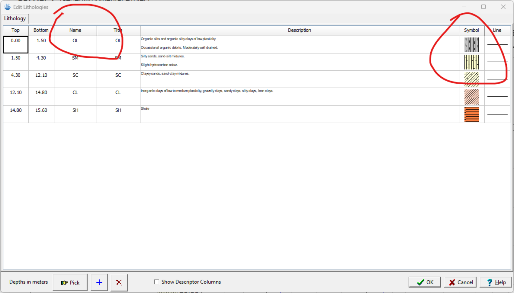
Before you can draw a cross-section you must first create your strata. Most strata have two boundaries, a top and a bottom. Lenses, intrusions, and faults have only one boundary.
If the cross-section is being auto-generated using data from WinLoG, most of the strata will be added using the unique layer names and lithologic symbols from WinLoG.
Beyond the strata automatically created from the WinLoG data, additional strata can be added. Click here to view a post dedicated to adding strata to a cross-section.
Drawing Strata Boundaries
There are three methods for drawing strata boundaries: fully drawn, snapped or assigned. To draw a boundary for a strata:
- Select the strata and then right click anywhere on the cross-section. Select Add Boundary, Top or Bottom from the popup menu.
- Draw the boundary using the mouse, starting at the left side of the cross-section and finishing on the right side of the cross-section.
- You can add as many points as desired and they do not have to be at the locations of the boreholes.
- When you are finished double click the mouse. Click the right mouse button and then select Previous Menu from the popup menu.
- That’s it, you have fully drawn this boundary.
Snapping Strata Boundaries
Snapped boundaries can be partially drawn and partially snapped. Snapped boundaries can include one or more different strata. Snapping is used to fix part of a strata’s boundary to a boundary of another strata. This approach allows the boundary of one strata to be fixed to the boundary of another. Making the input of strata boundaries quick and accurate. When drawing a boundary it is possible to draw part of the boundary and then snap to another existing strata boundary (i.e. fault).
To snap to an existing boundary:
- Double-click the left mouse button on the strata boundary.
- The remaining part of the boundary will then be formed from the snapped boundary.
Snapping to a portion of another boundary can be used to quickly draw pinchouts and uncomformities.
Assigning Strata Boundaries
In addition to snapping the strata boundaries can be assigned to the strata above or below. To assign one boundary to another you must first create your strata you will assign the boundary to:
- Once the first strata has been created, select the strata to be assigned.
- Click the right mouse button to display the popup menu and select Use Existing Strata, and either the Top or Bottom boundary. The pointer will change to a hand.
- Click on the strata that you want to assign this boundary to. If you are assigning the top boundary the strata should be above this strata and if you are assigning the bottom boundary the strata should be below this strata.
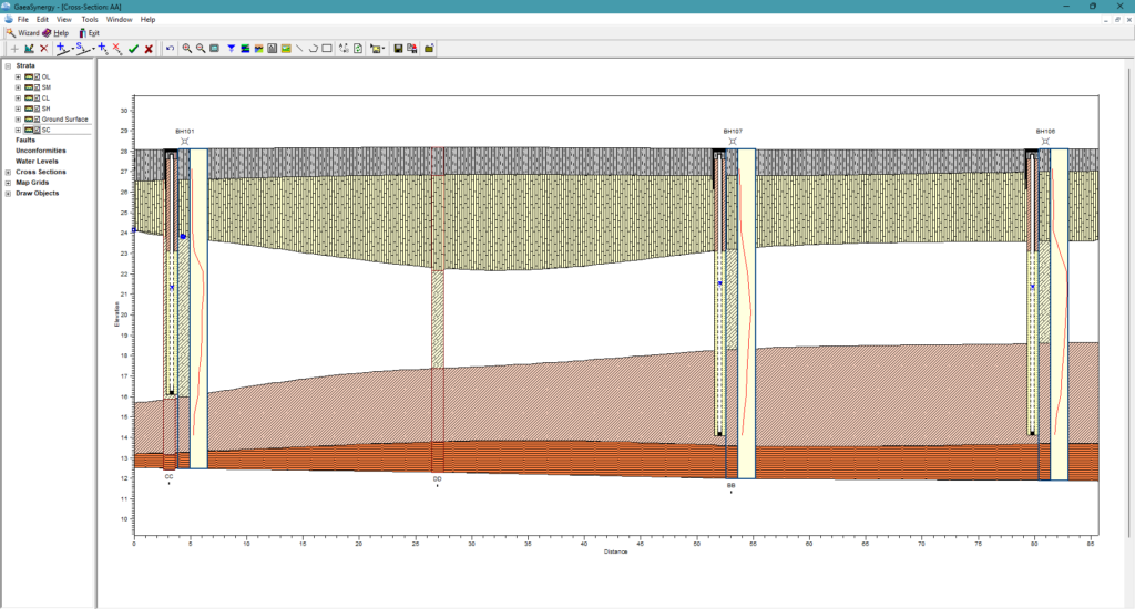
Editing Strata Boundaries
To begin modifying your cross-section, you must first ensure you are in Edit mode for the strata to be edited. Open the cross-section in the project, then click on the specific layer or strata you wish to modify. It will highlight or show “nodes” (small squares) at the vertices.
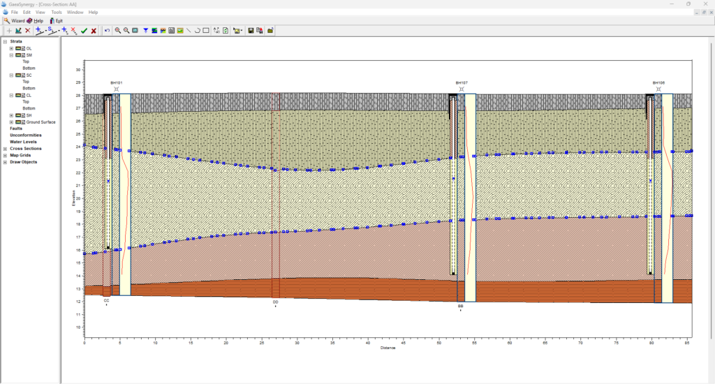
Moving and Adding Vertices
Once a strata is selected, you can change its boundaries to better fit your geological interpretation:
- To Move: Click and drag an existing node to a new location.
- To Add: Right-click on a line segment where you want more detail and select Add Points. This allows for more complex curves or pinching out of layers.
- To Delete: Right-click an unnecessary node and select Delete Point.
Modeling Complex Geology
When modeling complex geology in WinFence, layers don’t always run continuously across every borehole. Mastering “pinchouts” (where a layer thins and terminates), lenses, alteration zones, faults, and uncomformities is essential for creating accurate
Pinchouts
A pinch out occurs when a stratigraphic unit terminates between two boreholes in a cross-section. You can represent this manually or by using specific boundary assignments.
- Merging Boundaries: To “pinch out” a layer, use the mouse to drag the top and bottom nodes of the layer together until they meet at a single point.
- Snapping to Adjacent Strata: Use the Snapping Toggle to fix the terminating point of one layer directly onto the boundary of the layer above or below it. This ensures there are no mathematical “gaps” in your model.
- Discontinuous Segments: WinFence allows layers to be entered in multiple segments, meaning a layer can disappear in one part of the cross-section and reappear later if the data supports it.
Lenses
A lense only has one boundary, the boundary is normally formed by snapping it to the top or bottom boundary of another strata. To add the lense boundary:
- Select the lense and then right click anywhere in the cross section to display the popup menu.
- Select the Add Boundary menu item, the pointer will change to a cross hair.
- Click on the boundary of another strata to start drawing the lense (the boundary of the lense will be snapped to this strata from the left side of the cross-section to this point).
- Then add the points that define the lense.
- Finally snap the last point of the lense to the boundary of another strata or the same strata as before (the remaining boundary of the lense will be snapped to this strata from this point to the right side of the cross-section).
Faults and Uncomformities
Faults and uncomformities are treated as distinct line-based primitives in WinFence. They act as boundaries that can displace other strata.
- Creating a Fault or Uncomformity: Faults and uncomformities can be added by clicking on the Fault or Uncomformity button on the toolbar.
- Click on the location of the starting point of the first line segment. Then while holding down the left mouse button, drag the cursor to the end point of the first line segment and release the mouse button.
- Continue to add the other line segments the same way.
- After the end point of the last line segment had been added, either click the right mouse button or double clicking the left mouse button. The Edit Fault or Uncomformity form will then be displayed.
- In the Edit Fault form, you can check Use Curve Fit to turn straight segments into a smooth, natural curve.
- In the Edit Uncomformity form, you can control the amplitude and wave length of the line used to draw the unconformity.
- Editing Fault and Uncomformity Points: Once a fault or uncomformity is created, click it to reveal “marquee boxes” around its points. You can drag these points to adjust the horizontal and vertical position of the line.
- Snapping Layers to Faults and Uncomformities: Ensure your Snapping Toggle is active. This allows you to fix the ends of standard strata layers directly onto the fault line, making it easy to visualize vertical displacement or “offsets.”
Alteration Zones
Alteration zones (such as mineralization, contamination, or hydrocarbon zones) are managed differently than standard layers because they are defined by a single closed boundary rather than separate top and bottom lines.
Follow these steps to draw them manually or using the snapping features:
Step 1: Create the Alteration Zone Strata
- On the Edit menu select Strata and then Add Strata.
- Select Create New Strata on the Strata Type form.
- On the Strata definition form, select the strata type as Alteration Zone (or Mineralization, Hydrocarbon, or Contamination Zone). Then assign the relevant hatch patterns or colors.
Step 2: Define the Zone Path
- Manual Drawing: Click on your cross-section to place the first point of the alteration zone. Continue clicking to add vertices that define the perimeter of the zone.
- Single Boundary Rule: Unlike layers, you only draw one continuous line that loops back to its starting point to enclose the entire alteration area.
- Partial Snapping: You can draw parts of the zone manually and snap other sections directly to existing strata boundaries for hybrid accuracy.
Step 3: Refine and Edit Vertices
- Adjusting Points: After drawing, click on the boundary to reveal the individual nodes (small squares). You can drag these to reshape the zone.
- Adding/Deleting: Use the right-click menu on a line segment to add new vertices for more complex shapes, or select a node and delete it to smooth the boundary.
Tutorial Video
Watch this 7 minute tutorial on how to create and edit a cross-section using data from boring and well logs. Segments cover creating a cross-section using a path line and style; adding, deleting, and editing of strata; adding water levels; and use in 3D fence diagrams.
Summary
Editing boundaries in WinFence involves selecting the boundary tool, manipulating vertices for precision, and utilizing the Snapping function to align layers perfectly with borehole data. This process ensures that your geological cross-sections are both visually professional and scientifically accurate.
Related Articles
- Creating Fence Diagrams in WinFence: A Complete Guide to Subsurface Visualization
- Visualizing Stratigraphy Across Sites: A Complete Guide to Subsurface Correlation and Interpretation
- How Do I Use Project Views to Display Cross-Sections in GaeaSynergy?
- How Do I Create a Cross-Section in WinFence Using My WinLoG Data?
- How Do I Edit Strata Styles and Segments in WinFence?
- How do I Print or Export a Cross-section to a PDF in WinFence?
- How do I Add Strata to a Cross-section in WinFence?