
Introduction
Geotechnical engineering relies heavily on understanding subsurface conditions. Before constructing buildings, bridges, roads, tunnels, or other infrastructure, engineers must evaluate the soil and rock layers beneath a project site.
Because most of the subsurface cannot be directly observed, engineers depend on geological investigations to reveal the underground structure. Borehole drilling is one of the most common methods used to collect this information. Each borehole provides a vertical record of the materials encountered during drilling.
However, borehole logs alone do not provide a complete picture of subsurface geology. To understand how geological layers extend across a site, engineers and geologists construct geological cross-sections that connect borehole data.
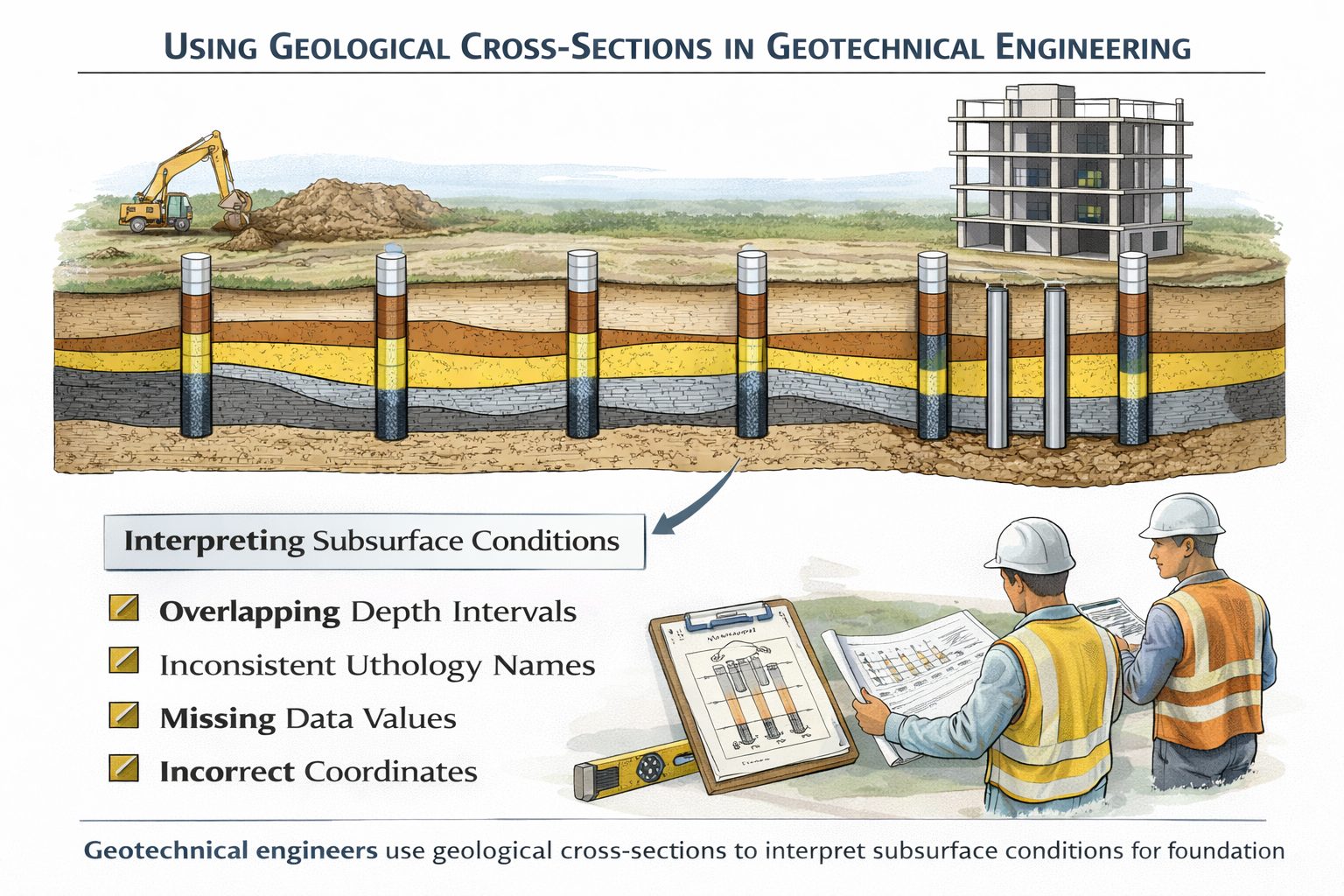
Geological cross-sections transform individual borehole logs into a continuous representation of subsurface stratigraphy. These diagrams allow engineers to visualize soil layers, identify potential geotechnical hazards, and design safe and stable foundations.
Cross-sections are essential for interpreting complex geological conditions and communicating subsurface information to project stakeholders.
This article explains how geological cross-sections are used in geotechnical engineering, the role they play in site investigations, and how engineers interpret these diagrams to support infrastructure design.
What Is a Geological Cross-Section?
A geological cross-section is a diagram that shows a vertical slice through the Earth’s subsurface.
Cross-sections are constructed by plotting borehole logs along a section line and connecting geological layers between them.
The resulting diagram illustrates how soil and rock layers extend beneath the ground surface.
Cross-sections typically display:
- ground surface elevation
- borehole locations
- lithology intervals
- groundwater levels
- interpreted geological layers
These diagrams allow engineers to visualize the geometry of subsurface materials and understand how geological units vary across a site.
In geotechnical engineering, cross-sections provide a bridge between raw borehole data and engineering analysis.
Role of Boreholes in Cross-Sections
Boreholes provide the primary data used to construct geological cross-sections.
During drilling operations, geologists or geotechnical engineers record observations about the materials encountered at different depths.
Typical borehole logs include:
- soil or rock type
- depth intervals
- sample collection depths
- groundwater observations
- laboratory test results
Each borehole represents a vertical sample of the subsurface.
When multiple boreholes are drilled across a site, their logs can be combined to create cross-sections that reveal the horizontal distribution of geological layers.
The spacing and location of boreholes influence the level of detail that can be interpreted from the cross-section.
Interpreting Soil Stratigraphy
One of the most important uses of geological cross-sections is interpreting soil stratigraphy.
Soil stratigraphy refers to the arrangement of soil layers beneath the ground surface.
Different soil types have different engineering properties. For example:
- clay may have low permeability and high compressibility
- sand may provide good drainage and moderate strength
- gravel may provide high load-bearing capacity
By examining cross-sections, engineers can identify the distribution of these materials across a site.
Understanding soil stratigraphy helps engineers determine whether the subsurface conditions are suitable for construction.
Foundation Design
Geological cross-sections play a critical role in foundation design.
Different types of foundations are used depending on the soil conditions beneath a structure.
For example:
- shallow foundations may be used when strong soil layers occur near the surface
- deep foundations such as piles may be required when weak soils extend to significant depths
Cross-sections help engineers determine the depth and thickness of soil layers and identify suitable bearing strata.
Engineers also examine cross-sections to identify weak layers that may cause settlement or instability.
Accurate geological interpretation ensures that foundations are designed to safely support structural loads.
Identifying Geotechnical Hazards
Geological cross-sections help engineers identify potential geotechnical hazards that may affect construction projects.
Some common hazards include:
Soft Clay Layers
Soft clay deposits can compress under load, causing building foundations to settle unevenly.
Cross-sections help identify the thickness and extent of these layers.
Loose Sand Deposits
Loose sand may be susceptible to liquefaction during earthquakes.
Cross-sections allow engineers to identify areas where liquefaction risks may occur.
Buried Channels
Ancient river channels filled with sand or gravel can create variations in soil conditions.
Cross-sections help detect these buried features.
Rock Surface Irregularities
Bedrock surfaces may be uneven due to erosion or geological processes.
Cross-sections help engineers understand the depth and shape of bedrock beneath the site.
Groundwater Conditions
Groundwater is another important factor in geotechnical engineering.
Borehole logs often record groundwater levels encountered during drilling.
These observations can be plotted on geological cross-sections.
Cross-sections help engineers understand:
- groundwater flow paths
- aquifer locations
- potential drainage issues
Groundwater conditions influence excavation stability, foundation design, and construction methods.
For example, high groundwater levels may require dewatering systems during excavation.
Cross-Sections in Slope Stability Analysis
Geological cross-sections are also used in slope stability analysis.
Slopes such as hillsides, embankments, and excavations may become unstable under certain conditions.
The stability of a slope depends on the arrangement of geological layers and groundwater conditions.
Cross-sections allow engineers to examine how soil layers extend through the slope.
By analyzing these layers, engineers can identify potential slip surfaces where slope failure may occur.
Geotechnical analysis software often uses cross-section geometry as input for slope stability calculations.
Cross-Sections in Infrastructure Projects
Large infrastructure projects require extensive geological investigations.
Examples include:
- highways
- railways
- bridges
- tunnels
- dams
These projects often span large areas with varying geological conditions.
Cross-sections help engineers understand how subsurface materials change along the project corridor.
For example, a highway project may require cross-sections at regular intervals to evaluate soil conditions along the route.
These cross-sections support decisions about foundation design, excavation methods, and ground improvement techniques.
Limitations of Geological Cross-Sections
Although cross-sections are powerful tools, they have limitations.
One major limitation is that cross-sections represent only a single slice through the subsurface.
Geological conditions may vary in directions that are not captured by the section line.
To address this limitation, engineers often create multiple cross-sections across a site.
Fence diagrams and three-dimensional models may also be used to provide a more complete view of subsurface geology.
Another limitation is uncertainty between boreholes.
Because boreholes provide discrete data points, geological layers must be interpreted between them.
Engineers must recognize that cross-sections represent interpretations rather than exact representations of the subsurface.
Digital Cross-Section Software
Modern geological software allows engineers to generate cross-sections directly from borehole databases.
These tools can automatically:
- plot borehole logs
- correlate lithology intervals
- generate cross-sections
Digital cross-sections can be easily updated when new borehole data becomes available.
Software tools also allow engineers to integrate cross-sections with three-dimensional geological models.
These digital workflows improve efficiency and support more accurate subsurface interpretation.
Best Practices for Using Cross-Sections
Several best practices can help engineers use geological cross-sections effectively.
First, ensure that borehole data is carefully validated before constructing cross-sections.
Second, use multiple cross-sections to analyze geological conditions from different perspectives.
Third, consider regional geology and depositional environments when interpreting layer correlations.
Fourth, communicate uncertainty clearly when borehole spacing is large.
Finally, update cross-sections whenever new borehole data becomes available.
Following these practices improves the reliability of geotechnical interpretations.
Integration with 3D Geological Models
Cross-sections often serve as the foundation for three-dimensional geological models.
By combining multiple cross-sections and borehole datasets, geologists can construct surfaces representing geological boundaries.
These surfaces are then used to build full three-dimensional models of subsurface geology.
3D models allow engineers to visualize complex geological structures and perform advanced analyses.
For example, groundwater flow simulations often rely on three-dimensional geological models derived from cross-section interpretations.
Conclusion
Geological cross-sections are essential tools in geotechnical engineering. They allow engineers to visualize subsurface conditions, interpret soil stratigraphy, and identify geological hazards that may affect construction projects.
By connecting borehole logs across a site, cross-sections provide valuable insight into the arrangement of soil and rock layers beneath the ground surface.
These interpretations support critical engineering decisions such as foundation design, slope stability analysis, and groundwater management.
Although cross-sections involve some level of interpretation, careful data preparation and geological expertise can produce reliable subsurface models.
As digital geological modeling tools continue to evolve, cross-sections will remain a fundamental method for understanding subsurface conditions and supporting safe infrastructure development.
Learn more about our Solutions
- GaeaSynergy Platform for Geoscientific Analysis
- WinLoG Borehole and Well Log Data Management
- WinFence Cross-section and Fence Diagram Visualization
Related Articles
- Geological Cross-Sections from Borehole Data: A Complete Engineering Guide
- Common Mistakes When Creating Geological Cross-Sections from Borehole Data
- How Borehole Spacing Affects Geological Cross-Section Accuracy
- Preparing Borehole Databases for Cross-Section Software
- How Lithological Correlation Works Between Boreholes
- Understanding Fence Diagrams in Geological Modeling
- Common Data Errors in Borehole Databases and How to Fix Them
- Borehole Coordinate Systems and Mapping for Geological Modeling
- Depth vs Elevation in Borehole Databases for Geological Modeling
- Interpreting Geological Variability Between Boreholes
- Building Geological Cross-Sections from Borehole Data: A Step-by-Step Workflow
- How Geological Software Interpolates Subsurface Layers Between Boreholes
- Borehole Data Visualization Techniques for Geological Modeling
- Managing Large Borehole Data Sets in Engineering Projects
- Understanding Pinch-Outs and Missing Geological Layers in Subsurface Interpretation