
Introduction
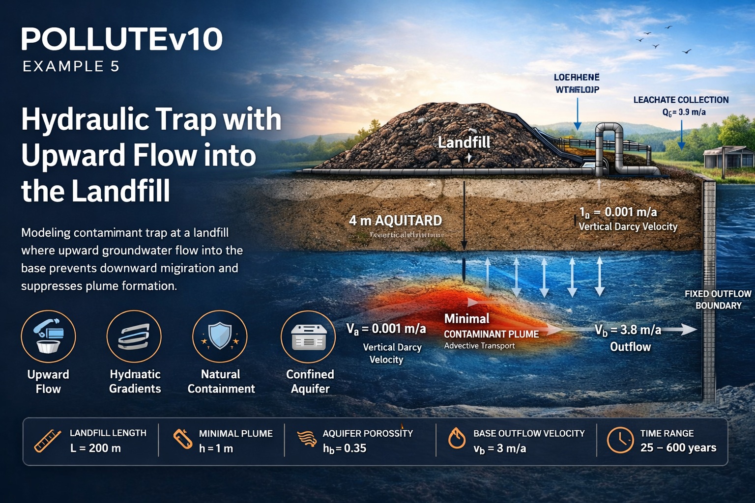
Example 5 demonstrates a fundamentally different hydrogeological condition compared to previous cases: a hydraulic trap, where groundwater flow is directed upward into the landfill rather than downward into the aquifer.
This scenario is critical in environmental modeling because it represents conditions where contaminant migration is naturally limited or even suppressed due to opposing hydraulic gradients. The example builds on Example 4 (finite mass source with leachate collection) but modifies flow conditions and aquifer properties to simulate this protective mechanism.
What is a Hydraulic Trap?
A hydraulic trap occurs when:
- The vertical hydraulic gradient is upward
- Groundwater flows into the landfill base
- Downward contaminant migration is restricted or reversed
In modeling terms, this is represented by a negative Darcy velocity.
Conceptual Model
The system consists of:
- A finite mass landfill source at the surface
- A 4 m thick aquitard
- A 1 m thick aquifer beneath
- A low permeability layer below the aquifer
- A hydraulic trap condition (upward flow)
Key Differences from Example 4:
- Upward flow instead of downward infiltration into aquifer
- Thinner aquifer (1 m vs 3 m)
- Slightly higher aquifer porosity (0.35)
- Landfill width simplified to W = 1 m (2D strip model)
Finite Mass Source (Same as Example 4)
The source term remains unchanged:
- Reference Height of Leachate: Hr = 7.5 m
- Source Concentration: 1000 mg/L
- Rate of Increase: Cr = 0
This ensures comparability between Example 4 and Example 5.
Hydraulic Conditions
Vertical Darcy Velocity (Key Change)
- The negative sign indicates upward flow
- This is the defining characteristic of the hydraulic trap
Leachate Collection System
Because upward flow limits infiltration into the subsurface:
Where:
Result:
This means:
- Nearly all infiltrating water is captured
- Minimal contaminant mass enters the subsurface
Groundwater Flow Balance
Upgradient Inflow:
Downgradient Outflow:
Substituting values:
Interpretation:
- Outflow is reduced due to upward flow
- The aquifer receives less contaminant loading
Model Parameters
| Property | Symbol | Value | Units |
|---|---|---|---|
| Darcy Velocity | va | -0.001 | m/a |
| Diffusion Coefficient | D | 0.01 | m²/a |
| Distribution Coefficient | Kd | 0 | cm³/g |
| Soil Porosity | n | 0.4 | – |
| Dry Density | ρd | 1.5 | g/cm³ |
| Soil Thickness | H | 4 | m |
| Sub-layers | – | 4 | – |
| Source Concentration | co | 1000 | mg/L |
| Rate of Increase | cr | 0 | mg/L/a |
| Reference Height | Hr | 7.5 | m |
| Leachate Collected | Qc | 0.3 | m/a |
| Landfill Length | L | 200 | m |
| Landfill Width | W | 1 | m |
| Aquifer Thickness | h | 1 | m |
| Aquifer Porosity | nb | 0.35 | – |
| Base Outflow Velocity | vb | 3.8 | m/a |
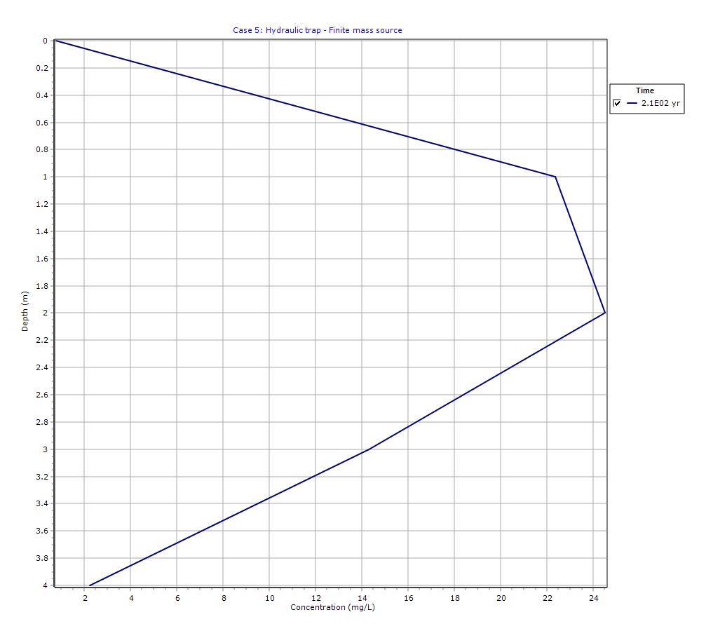
Graphical Output: Depth vs Concentration
PDF Report
 Loading…
Interpretation of Results
1. Upward Flow Suppresses Contamination
The hydraulic trap:
- Prevents downward contaminant migration
- Reduces plume formation in the aquifer
- Acts as a natural containment mechanism
2. Reduced Aquifer Impact
Compared to Example 4:
- Plume size is significantly smaller
- Concentrations are lower
- Transport is diffusion-dominated rather than advective
3. Importance of Aquifer Thickness
With only 1 m thickness:
- Less storage capacity
- Faster response to hydraulic changes
- Greater sensitivity to vertical gradients
4. Engineering Implications
Hydraulic traps can be:
- Naturally occurring
- Engineered using pumping systems
They are often used in:
- Containment strategies
- Remediation design
- Groundwater protection systems
Practical Applications
This modeling scenario is highly relevant for:
- Landfill sites with upward gradients
- Confined or semi-confined aquifers
- Sites underlain by low permeability layers
- Remediation systems using hydraulic control
- Advanced Phase II ESA and risk assessments
Comparison: Example 4 vs Example 5
| Feature | Example 4 | Example 5 |
|---|---|---|
| Flow Direction | Downward | Upward |
| Darcy Velocity | +0.03 m/a | -0.001 m/a |
| Aquifer Thickness | 3 m | 1 m |
| Leachate Collection | Partial | Near complete |
| Plume Development | Significant | Minimal |
| Risk Level | Higher | Lower |
Key Takeaways
- Hydraulic traps are a powerful natural or engineered control on contaminant migration
- Upward gradients can significantly reduce environmental risk
- POLLUTEv10 effectively models complex flow reversals
- Comparing scenarios helps inform design and regulatory decisions
Learn more about our Contaminant Transport Modeling Solutions
POLLUTE Examples
- POLLUTEv10 Example 1: Modeling a U.S. RCRA Subtitle D Landfill
- POLLUTEv10 Example 2: Pure Diffusion in a Soil Layer (No Sorption)
- POLLUTEv10 Example 3: Advection + Diffusion with Aquifer Mixing
- POLLUTEv10 Example 4: Finite Mass Source with Leachate Collection System
- POLLUTEv10 Example 6: Fractured Layer with Sorption and Reactive Transport
- POLLUTEv10 Example 7: Lateral Migration of a Radioactive Contaminant in Fractured Rock
- POLLUTEv10 Example 8: Laboratory Diffusion of Potassium in Clay
- POLLUTEv10 Example 9: Diffusion with Freundlich Non-Linear Sorption (Phenol in Clay)
- POLLUTEv10 Example 10: Time-Varying Advective–Dispersive Transport from a Landfill
- POLLUTEv10 Example 11: Time-Varying Source Concentration with Diffusion (Chloride in Clay)
- POLLUTEv10 Example 12: Fractured Media Transport vs Analytical Solution (Tang et al., 1981)
- POLLUTEv10 Example 13: 2D Plane Dispersion vs Analytical Solution (TDAST)
- POLLUTEv10 Example 14: Modeling a Landfill with Primary and Secondary Leachate Collection Using Passive Sink
- POLLUTEv10 Example 15: Modeling Leachate Collection System Failure Using Variable Properties and Passive Sink
- POLLUTEv10 Example 16: Monte Carlo Simulation of Leachate Collection System Failure Timing
- POLLUTEv10 Example 17: Modeling a Landfill with Composite Liners and Dual Leachate Collection Systems
- POLLUTEv10 Example 18: Modeling Phase Change in a Secondary Leachate Collection System
- POLLUTEv10 Example 19: Multiphase Diffusion of Toluene Through a Geomembrane System
- POLLUTEv10 Example 20: Sensitivity Analysis of Primary Leachate Collection System Failure