
Introduction
POLLUTEv10 Example 14 demonstrates an advanced application of contaminant transport modeling using the Passive Sink special feature. This scenario simulates a landfill equipped with both primary and secondary leachate collection systems, incorporating layered hydrogeologic conditions and a finite contaminant source.
The example is particularly useful for environmental engineers and hydrogeologists seeking to understand how engineered systems influence contaminant migration in subsurface environments.
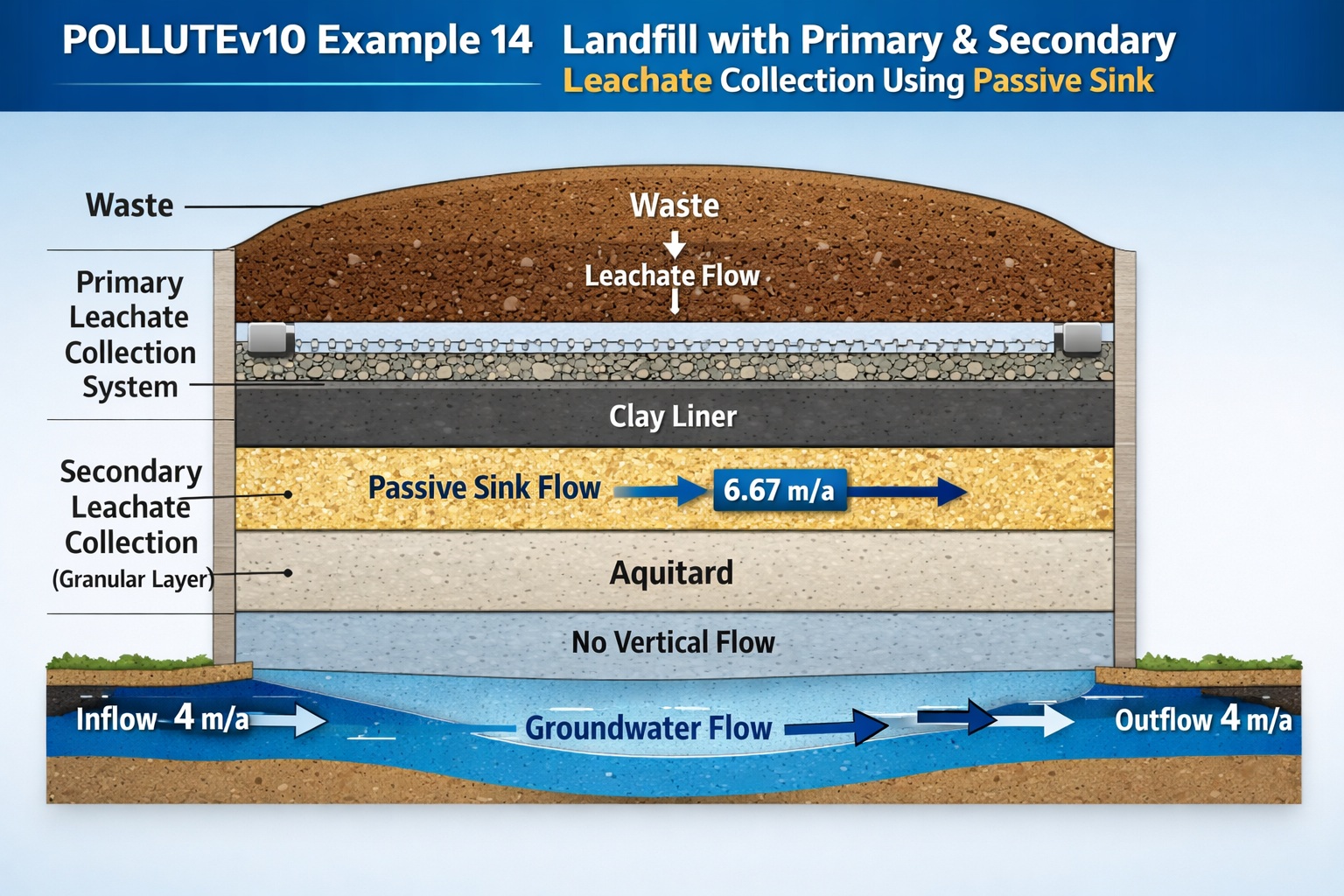
Conceptual Model Overview
The model represents a hypothetical landfill with the following characteristics:
- Finite mass of a conservative contaminant
- Primary and secondary leachate collection systems
- Underlying aquifer with fixed outflow
- Use of a passive sink to simulate leachate removal
Key Assumptions
- Peak leachate concentration is reached early
- No increase in concentration over time
- Flow conditions are steady-state
- Transport includes advection and diffusion
Source Term Characterization
The landfill contains waste with the following properties:
- Waste thickness: 6.25 m
- Waste density: 600 kg/m³
- Contaminant fraction: 0.2%
Total Contaminant Mass per Unit Area
Reference Height of Leachate
Where:
Because peak concentration occurs early:
- Rate of increase in concentration:
Leachate Generation and Collection
The water balance in the landfill is defined as:
- Infiltration through cover: 0.3 m/a
- Exfiltration through base: 0.01 m/a
Volume of Leachate Collected
This collected leachate is managed by the primary system, while the secondary system is modeled using a passive sink.
Hydrogeologic Stratigraphy
The subsurface consists of:
| Layer | Description | Thickness |
|---|---|---|
| Layer 1 | Clay layer | 1 m |
| Layer 2 | Granular layer (secondary LCS) | 0.3 m |
| Layer 3 | Aquitard | 2 m |
| Aquifer | Flowing groundwater zone | 1 m |
Flow Conditions
Vertical Flow
- From landfill to secondary system:
- From secondary system to aquifer:
This implies the water table is located at the base of the secondary system.
Horizontal Flow in Passive Sink Layer
The passive sink (granular layer) induces lateral flow:
This represents efficient lateral drainage within the secondary leachate collection system.
Aquifer Flow
- Upgradient inflow: 4 m/a
- Down-gradient outflow:
Thus, aquifer flow remains constant beneath the landfill.
Passive Sink Layer Configuration
The Passive Sink option divides the system into three computational layers:
- Layer 1 (Clay Layer)
- Vertical flow only: 0.01 m/a downward
- No horizontal flow
- Layer 2 (Granular Secondary LCS)
- Horizontal flow: 6.67 m/a
- Represents leachate collection
- Layer 3 (Aquitard)
- No advective flow
- Diffusion dominates transport
Model Parameters
| Property | Symbol | Value | Units |
|---|---|---|---|
| Darcy Velocity | va | Variable | m/a |
| Sink Velocity | vs | Variable | m/a |
| Diffusion Coefficient | D | Variable | m²/a |
| Distribution Coefficient | Kd | 0 | cm³/g |
| Soil Porosity | n | 0.4 | – |
| Granular Porosity | n | 0.3 | – |
| Dry Density | ρd | 1.5 | g/cm³ |
| Source Concentration | c₀ | 1000 | mg/L |
| Ref. Height | Hr | 7.5 | m |
| Leachate Collected | Qc | 0.29 | m/a |
| Landfill Length | L | 200 | m |
| Aquifer Velocity | vb | 4 | m/a |
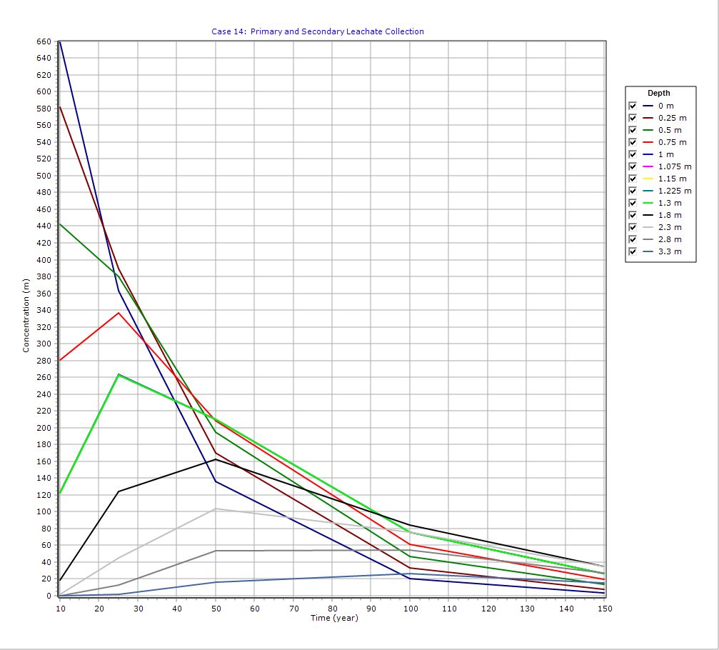
Graphical Output: Concentration vs Time
PDF Report
 Loading…
Key Insights
- The secondary leachate collection system significantly reduces vertical contaminant migration.
- The passive sink approach effectively simulates engineered drainage layers.
- With zero vertical flow below the secondary system, contaminants are largely contained above the aquifer.
- Diffusion becomes the dominant transport mechanism in deeper layers.
Important Modeling Considerations
⚠️ This example is illustrative only and should not be used as a design standard.
Each landfill system is unique, and accurate modeling requires:
- Site-specific hydrogeologic data
- Proper calibration of transport parameters
- Expertise in contaminant transport processes
The Passive Sink feature should only be used by professionals with a strong hydrogeotechnical background.
Conclusion
POLLUTEv10 Example 14 highlights the importance of incorporating engineered systems—such as secondary leachate collection layers—into contaminant transport models. By using the Passive Sink feature, this example provides a realistic framework for simulating leachate interception and lateral drainage, improving our understanding of landfill performance and environmental protection.
Learn more about our Contaminant Transport Modeling Solutions
POLLUTE Examples
- POLLUTEv10 Example 1: Modeling a U.S. RCRA Subtitle D Landfill
- POLLUTEv10 Example 2: Pure Diffusion in a Soil Layer (No Sorption)
- POLLUTEv10 Example 3: Advection + Diffusion with Aquifer Mixing
- POLLUTEv10 Example 4: Finite Mass Source with Leachate Collection System
- POLLUTEv10 Example 5: Hydraulic Trap (Upward Flow into the Landfill)
- POLLUTEv10 Example 6: Fractured Layer with Sorption and Reactive Transport
- POLLUTEv10 Example 7: Lateral Migration of a Radioactive Contaminant in Fractured Rock
- POLLUTEv10 Example 8: Laboratory Diffusion of Potassium in Clay
- POLLUTEv10 Example 9: Diffusion with Freundlich Non-Linear Sorption (Phenol in Clay)
- POLLUTEv10 Example 10: Time-Varying Advective–Dispersive Transport from a Landfill
- POLLUTEv10 Example 11: Time-Varying Source Concentration with Diffusion (Chloride in Clay)
- POLLUTEv10 Example 12: Fractured Media Transport vs Analytical Solution (Tang et al., 1981)
- POLLUTEv10 Example 13: 2D Plane Dispersion vs Analytical Solution (TDAST)
- POLLUTEv10 Example 15: Modeling Leachate Collection System Failure Using Variable Properties and Passive Sink
- POLLUTEv10 Example 16: Monte Carlo Simulation of Leachate Collection System Failure Timing
- POLLUTEv10 Example 17: Modeling a Landfill with Composite Liners and Dual Leachate Collection Systems
- POLLUTEv10 Example 18: Modeling Phase Change in a Secondary Leachate Collection System
- POLLUTEv10 Example 19: Multiphase Diffusion of Toluene Through a Geomembrane System
- POLLUTEv10 Example 20: Sensitivity Analysis of Primary Leachate Collection System Failure
Comparison between POLLUTE and MIGRATE
- MIGRATEv10 vs POLLUTEv10: Pure Diffusion Comparison
- MIGRATEv10 vs POLLUTEv10: Advective–Diffusive Transport Comparison
- MIGRATEv10 vs POLLUTEv10: Finite Mass Source Comparison
- MIGRATEv10 vs POLLUTEv10: Hydraulic Trap (Finite Mass Source) Comparison
- MIGRATEv10 vs POLLUTEv10: Fractured Layer with Sorption Comparison