
Introduction
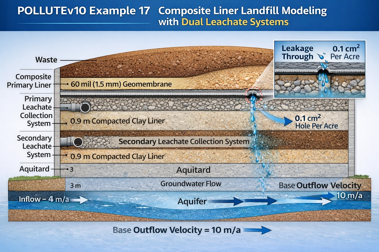
POLLUTEv10 Example 17 demonstrates how to model a landfill incorporating a composite primary liner, primary and secondary leachate collection systems, and a compacted clay secondary liner. This example introduces a more engineered and realistic landfill design, reflecting modern containment practices.
A key feature is the use of the Giroud et al. (1992) leakage method, which allows POLLUTEv10 to automatically calculate leakage through defects in the geomembrane.
Conceptual Model Overview
This model represents a landfill with:
- Composite primary liner (geomembrane + clay)
- Primary leachate collection system
- Secondary leachate collection system
- Secondary compacted clay liner
- Underlying aquitard and aquifer
Composite Primary Liner Design
The primary liner consists of:
- 60 mil (1.5 mm) geomembrane
- 0.9 m compacted clay liner
- Good contact between layers
Geomembrane Defects
- Hole area: 0.1 cm²
- Frequency: ~1 per acre (2.5 per hectare)
Even with high-quality installation, small defects are assumed, allowing controlled leakage estimation.
Leakage Through Composite Liner
POLLUTEv10 uses the Giroud et al. (1992) method to calculate leakage:
- Accounts for:
- Hole size and frequency
- Head on liner
- Clay permeability
- Calculations are performed automatically
Key Insight
Composite liners dramatically reduce leakage compared to single-layer systems, even with defects.
Secondary Containment System
Below the primary liner:
Secondary Leachate Collection System
- Thickness: 0.3 m
- High permeability granular layer
- Provides leakage interception
Secondary Clay Liner
- Thickness: 0.9 m
- Hydraulic conductivity:
This acts as a backup barrier to prevent contaminant migration.
Subsurface Conditions
Below the landfill:
- Aquitard thickness: 3 m
- Aquifer thickness: 3 m
Groundwater conditions:
- Groundwater level at top of aquitard
- Flow defined by Base Outflow Velocity
Source Term and Boundary Conditions
- Contaminant type: volatile organic compound (VOC)
- Source concentration: 1500 μg/L
- Source behavior: constant over time
Hydraulic Heads
- Head on primary liner: 0.3 m
- Head on secondary liner: 0.3 m
- Groundwater elevation: 3 m
Aquifer Flow Conditions
- Controlled by Base Outflow Velocity (vb)
- Value:
This parameter represents horizontal groundwater movement beneath the landfill.
Material Properties
Clay Layers
- Thickness: 0.9 m
- Diffusion coefficient: 0.02 m²/a
- Distribution coefficient: 0.5 mL/g
- Porosity: 0.35
- Dry density: 1.9 g/cm³
Collection System
- Thickness: 0.3 m
- Dispersion coefficient: 100 m²/a
- Porosity: 0.3
- No sorption (Kd = 0)
Aquitard
- Thickness: 3 m
- Hydraulic conductivity: 1 × 10⁻⁵ m/s
- Diffusion coefficient: 0.02 m²/a
Key Modeling Features
1. Composite Liner Leakage Modeling
- Realistic simulation of geomembrane defects
- Automatic leakage calculation
2. Dual Leachate Collection Systems
- Primary system manages bulk leachate
- Secondary system captures leakage
3. Multi-Barrier Protection
- Geomembrane
- Clay liners
- Collection systems
- Natural geologic layers
Data Entry Approach in POLLUTEv10
This example uses the:
👉 Primary and Secondary Liner Landfill Template
Key Difference from Previous Examples
- Data is entered through a specialized interface
- Simplifies setup of:
- Composite liners
- Leakage parameters
- Multi-layer systems
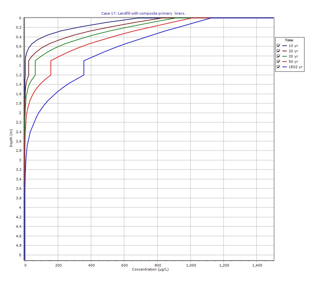
Graphical Output: Depth vs Concentration
PDF Report
 Loading…
Key Insights
- Composite liners significantly reduce leakage risk
- Even small defects can contribute to long-term contaminant migration
- Secondary systems provide critical redundancy
- Aquifer protection depends on:
- Liner integrity
- Collection efficiency
- Hydrogeologic conditions
Practical Implications
This modeling approach is essential for:
- Modern landfill design
- Regulatory compliance
- Risk assessment
- Long-term performance evaluation
It reflects best practices in engineered containment systems.
Important Disclaimer
⚠️ This example is hypothetical and for demonstration only.
- Not a design standard
- Not universally applicable
- Requires site-specific calibration
Accurate application requires expertise in:
- Hydrogeology
- Geotechnical engineering
- Contaminant transport modeling
Conclusion
POLLUTEv10 Example 17 demonstrates how advanced landfill designs—featuring composite liners and dual leachate collection systems—can be effectively modeled. By incorporating leakage through geomembrane defects and multi-layer protection systems, this example provides a realistic framework for evaluating landfill performance and environmental protection.
Learn more about our Contaminant Transport Modeling Solutions
POLLUTE Examples
- POLLUTEv10 Example 1: Modeling a U.S. RCRA Subtitle D Landfill
- POLLUTEv10 Example 2: Pure Diffusion in a Soil Layer (No Sorption)
- POLLUTEv10 Example 3: Advection + Diffusion with Aquifer Mixing
- POLLUTEv10 Example 4: Finite Mass Source with Leachate Collection System
- POLLUTEv10 Example 5: Hydraulic Trap (Upward Flow into the Landfill)
- POLLUTEv10 Example 6: Fractured Layer with Sorption and Reactive Transport
- POLLUTEv10 Example 7: Lateral Migration of a Radioactive Contaminant in Fractured Rock
- POLLUTEv10 Example 8: Laboratory Diffusion of Potassium in Clay
- POLLUTEv10 Example 9: Diffusion with Freundlich Non-Linear Sorption (Phenol in Clay)
- POLLUTEv10 Example 10: Time-Varying Advective–Dispersive Transport from a Landfill
- POLLUTEv10 Example 11: Time-Varying Source Concentration with Diffusion (Chloride in Clay)
- POLLUTEv10 Example 12: Fractured Media Transport vs Analytical Solution (Tang et al., 1981)
- POLLUTEv10 Example 13: 2D Plane Dispersion vs Analytical Solution (TDAST)
- POLLUTEv10 Example 14: Modeling a Landfill with Primary and Secondary Leachate Collection Using Passive Sink
- POLLUTEv10 Example 15: Modeling Leachate Collection System Failure Using Variable Properties and Passive Sink
- POLLUTEv10 Example 16: Monte Carlo Simulation of Leachate Collection System Failure Timing
- POLLUTEv10 Example 18: Modeling Phase Change in a Secondary Leachate Collection System
- POLLUTEv10 Example 19: Multiphase Diffusion of Toluene Through a Geomembrane System
- POLLUTEv10 Example 20: Sensitivity Analysis of Primary Leachate Collection System Failure