
Introduction
Accurate spatial data is essential for interpreting subsurface geology. Boreholes provide valuable information about soil and rock layers beneath the ground surface, but without accurate location data, this information cannot be properly integrated into geological models.
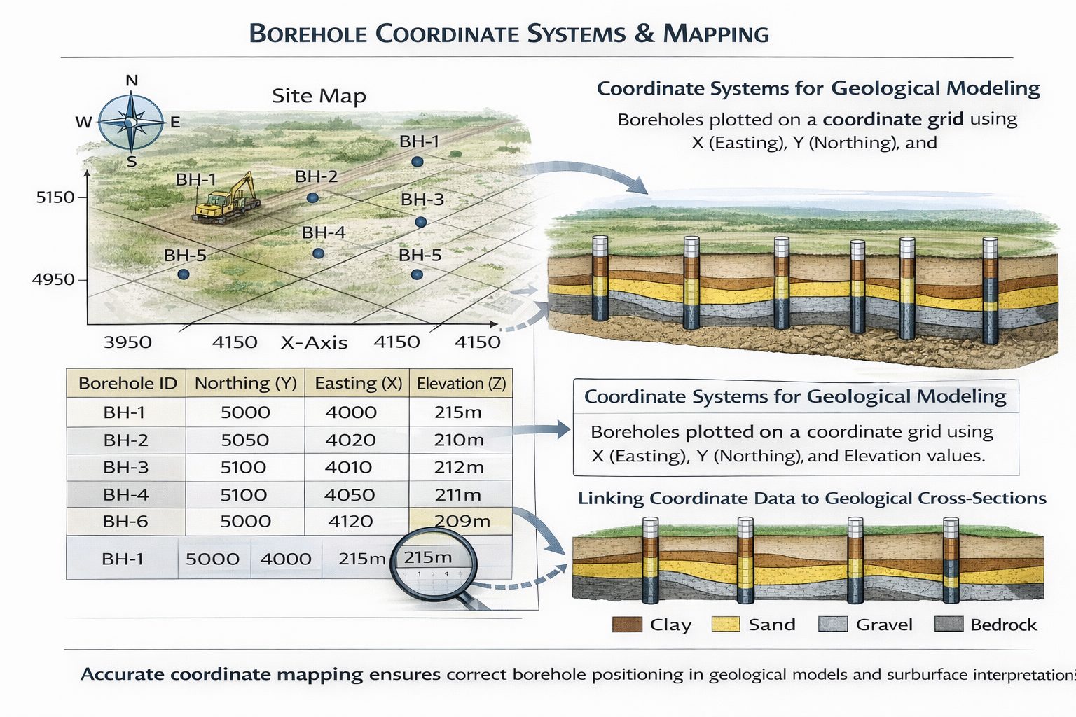
Borehole coordinates allow geologists and engineers to position boreholes within maps, cross-sections, and three-dimensional geological models. These coordinates define where each borehole is located in space, enabling geological software to reconstruct the subsurface structure between drilling locations.
In modern geotechnical investigations, borehole coordinates are typically recorded using surveying equipment, GPS systems, or digital mapping tools. These coordinates are then stored within borehole databases and used by geological modeling software to generate cross-sections, fence diagrams, and subsurface models.
However, managing borehole coordinate systems can be complex. Different coordinate systems may be used in different datasets, and inconsistencies can cause significant errors in geological models.
Understanding how coordinate systems work and how they affect geological modeling is therefore essential for anyone working with borehole data.
This article explains the role of borehole coordinates in geological interpretation, the different types of coordinate systems used in geotechnical investigations, and the best practices for managing spatial data in geological databases.
Why Borehole Coordinates Matter
Borehole logs describe vertical geological conditions, but they do not provide spatial context on their own. Without coordinate information, borehole data cannot be positioned relative to other boreholes or mapped within a project area.
Borehole coordinates allow geologists to:
- map borehole locations
- create geological cross-sections
- generate fence diagrams
- build three-dimensional geological models
These coordinates define the horizontal position of each borehole and allow software to calculate distances between drilling locations.
If borehole coordinates are incorrect or inconsistent, geological models may be distorted.
For example, a borehole plotted in the wrong location may cause cross-sections to misrepresent geological layers or incorrectly correlate materials between boreholes.
Ensuring that borehole coordinates are accurate and consistent is therefore essential for reliable subsurface modeling.
Components of Borehole Spatial Data
Borehole spatial data typically includes three key components.
Easting Coordinate
The easting value represents the horizontal position of a borehole in the east-west direction within a coordinate system.
This value measures how far the borehole is located east of a reference point within the coordinate grid.
Northing Coordinate
The northing value represents the borehole’s position in the north-south direction.
This coordinate measures how far the borehole is located north of a reference point within the coordinate system.
Ground Elevation
Ground elevation represents the vertical position of the borehole relative to a reference datum, usually sea level.
Elevation data is essential for converting depth measurements into absolute elevations when constructing geological cross-sections.
Together, these three components allow boreholes to be positioned accurately within three-dimensional space.
Types of Coordinate Systems Used in Geotechnical Investigations
Several types of coordinate systems are commonly used in geological and engineering projects.
Geographic Coordinate Systems
Geographic coordinate systems use latitude and longitude values to define locations on the Earth’s surface.
Latitude measures the distance north or south of the equator, while longitude measures the distance east or west of the prime meridian.
Although geographic coordinates are widely used for global positioning systems (GPS), they are not always ideal for engineering projects because distances between coordinates are not uniform across the Earth’s surface.
Projected Coordinate Systems
Projected coordinate systems convert the curved surface of the Earth into a flat map projection.
These systems use linear units such as meters or feet to measure distances, making them more suitable for engineering calculations.
Common projected coordinate systems include:
- Universal Transverse Mercator (UTM)
- State Plane Coordinate Systems
- national grid systems used in different countries
Most geotechnical projects use projected coordinate systems because they allow accurate distance and area measurements.
Local Coordinate Systems
Some projects use local coordinate systems established specifically for the site investigation.
Local grids may be defined relative to a reference point within the project area.
Although local coordinate systems can simplify site mapping, they must be carefully documented so that borehole locations can be converted into regional coordinate systems if necessary.
Mapping Boreholes in GIS
Geographic Information Systems (GIS) are widely used to manage spatial data in geological investigations.
GIS software allows engineers and geologists to visualize borehole locations within maps and combine them with other spatial datasets.
For example, GIS maps may include:
- borehole locations
- geological maps
- topographic data
- groundwater monitoring points
- environmental sampling locations
By integrating borehole data with GIS systems, geologists can analyze spatial patterns in subsurface conditions and identify areas where additional drilling may be required.
GIS platforms also allow borehole coordinates to be exported to geological modeling software.
Borehole Coordinates in Geological Cross-Sections
Borehole coordinates play a critical role when constructing geological cross-sections.
Cross-sections are typically drawn along a section line that connects several boreholes.
The coordinates of each borehole determine how it is projected onto the section line.
The distance between boreholes along the section line affects how geological layers are interpreted between them.
If borehole coordinates are inaccurate, the cross-section geometry may be distorted.
For example, boreholes may appear closer together or farther apart than they actually are.
Accurate coordinates ensure that cross-sections represent subsurface conditions correctly.
Borehole Coordinates in Fence Diagrams
Fence diagrams combine multiple cross-sections into a three-dimensional framework.
Because fence diagrams rely on intersecting section lines, accurate borehole coordinates are essential.
The spatial arrangement of boreholes determines how cross-sections intersect and how geological layers extend across the site.
Incorrect coordinates can cause cross-sections to intersect in unrealistic ways, making geological interpretation difficult.
Proper spatial data management ensures that fence diagrams accurately represent subsurface conditions.
Borehole Coordinates in 3D Geological Models
Three-dimensional geological models rely heavily on borehole coordinate data.
These models use borehole locations to construct surfaces representing geological layer boundaries.
For example, a geological modeling program may use borehole coordinates and lithology intervals to generate surfaces representing the top of a clay layer or the base of a sand deposit.
The accuracy of these surfaces depends directly on the accuracy of the borehole coordinates.
If boreholes are mislocated, the resulting geological surfaces may be distorted.
Maintaining accurate spatial data is therefore critical for reliable 3D modeling.
Common Coordinate Errors in Borehole Databases
Several common errors can occur when managing borehole coordinate data.
Incorrect Coordinate Systems
If borehole coordinates are recorded using different coordinate systems, the locations may appear in the wrong place when mapped.
For example, mixing geographic coordinates with projected coordinates can produce large spatial errors.
Swapped Easting and Northing Values
Data entry mistakes may cause easting and northing values to be swapped.
This error can place boreholes far from their true locations.
Missing Elevation Data
If ground elevation values are missing, cross-sections may place geological layers at incorrect depths.
Unit Conversion Errors
Coordinate units must be consistent across the dataset. Mixing meters and feet can cause spatial distortions.
Quality Control for Borehole Coordinates
Quality control procedures help ensure that borehole coordinate data is accurate.
Common quality control steps include:
- verifying coordinate systems
- checking coordinate ranges
- mapping borehole locations in GIS
- comparing coordinates with site maps
Visualizing borehole locations on a map is one of the most effective ways to detect coordinate errors.
If boreholes appear outside the project area or clustered incorrectly, coordinate issues may exist.
Best Practices for Managing Borehole Coordinates
Several best practices can help maintain accurate borehole coordinate data.
First, record borehole coordinates using reliable surveying or GPS equipment.
Second, ensure that all coordinates use the same coordinate system.
Third, document the coordinate system and vertical datum used for the project.
Fourth, perform quality control checks when importing borehole data into databases.
Finally, integrate borehole coordinates with GIS systems to visualize spatial relationships.
Following these practices ensures that borehole locations remain accurate and consistent.
Integration with Digital Geological Workflows
Modern geological workflows integrate borehole databases, GIS systems, and geological modeling software.
In these workflows, borehole coordinate data serves as the link between spatial mapping and subsurface modeling.
Borehole databases provide lithology intervals and elevation data, while GIS systems provide spatial context.
Geological modeling software then uses this information to generate cross-sections and 3D models.
Maintaining consistent coordinate systems across these tools ensures that geological interpretations remain accurate.
Conclusion
Borehole coordinate systems play a critical role in geological and geotechnical investigations. Accurate spatial data allows boreholes to be mapped, analyzed, and integrated into cross-sections, fence diagrams, and three-dimensional geological models.
Understanding coordinate systems, managing spatial data carefully, and performing quality control checks are essential steps in preparing borehole databases for geological modeling.
When borehole coordinates are accurate and consistent, engineers and geologists can build reliable subsurface models that support infrastructure design, environmental investigations, and resource exploration.
As digital geological workflows continue to evolve, effective management of spatial data will remain a fundamental component of subsurface interpretation.
Learn more about our Solutions
- GaeaSynergy Platform for Geoscientific Analysis
- WinLoG Borehole and Well Log Data Management
- WinFence Cross-section and Fence Diagram Visualization
Related Articles
- GaeaSynergy: Integrated Geological, Geotechnical, and Environmental Data Management Platform
- Subsurface Visualization: Turning Borehole Data into Clear Geological Insight
- Geological Cross-Sections from Borehole Data: A Complete Engineering Guide
- Common Mistakes When Creating Geological Cross-Sections from Borehole Data
- How Borehole Spacing Affects Geological Cross-Section Accuracy
- Preparing Borehole Databases for Cross-Section Software
- How Lithological Correlation Works Between Boreholes
- Understanding Fence Diagrams in Geological Modeling
- Common Data Errors in Borehole Databases and How to Fix Them
- Using Geological Cross-Sections in Geotechnical Engineering
- Depth vs Elevation in Borehole Databases for Geological Modeling
- Interpreting Geological Variability Between Boreholes
- Building Geological Cross-Sections from Borehole Data: A Step-by-Step Workflow
- How Geological Software Interpolates Subsurface Layers Between Boreholes
- Borehole Data Visualization Techniques for Geological Modeling
- Managing Large Borehole Data Sets in Engineering Projects
- Understanding Pinch-Outs and Missing Geological Layers in Subsurface Interpretation