
Introduction
Installation of monitoring wells is one of the most critical components of a Phase II Environmental Site Assessment (ESA), particularly when groundwater contamination is suspected or confirmed. While soil sampling provides a snapshot of subsurface conditions, monitoring wells allow environmental professionals to observe, measure, and sample groundwater over time—transforming a one-time investigation into a long-term data collection system.
Monitoring wells serve as engineered access points into the subsurface. When properly designed and installed, they provide reliable, repeatable, and representative groundwater data essential for risk assessment, contaminant delineation, and remediation planning. In jurisdictions such as Ontario Regulation 153/04, strict technical requirements govern how these wells must be installed and documented to ensure data integrity and environmental protection.
This article provides a comprehensive overview of monitoring well installation for Phase II ESAs, including purpose, materials, design considerations, installation procedures, and regulatory compliance.
Purpose of Monitoring Wells
Monitoring wells are not simply holes in the ground—they are precision-built sampling systems designed to isolate and evaluate specific hydrogeologic conditions. Their purpose can be broken down into three primary functions:
1. Groundwater Sampling
Monitoring wells allow for the collection of groundwater samples that are representative of in-situ conditions. These samples are analyzed in laboratories to determine the presence and concentration of contaminants such as:
- Petroleum hydrocarbons (PHCs)
- Volatile organic compounds (VOCs)
- Metals and inorganics
- Chlorinated solvents
Proper well design ensures that samples are not influenced by external contamination or well construction materials.
2. Hydraulic Characterization
One of the most important uses of monitoring wells is measuring groundwater elevations. By installing multiple wells across a site, environmental professionals can:
- Determine the depth to groundwater
- Establish hydraulic gradients
- Define groundwater flow direction
This information is critical for predicting contaminant migration pathways and assessing potential risks to receptors such as drinking water sources or nearby ecosystems.
3. Long-Term Monitoring
Monitoring wells are typically permanent or semi-permanent installations. They provide access for:
- Periodic sampling programs
- Seasonal groundwater level monitoring
- Performance monitoring of remediation systems
In many cases, wells remain in place for years as part of ongoing environmental management strategies.
Materials and Design
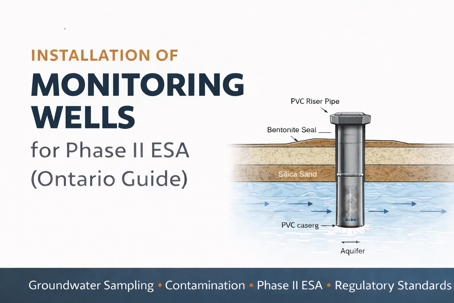
The reliability of a monitoring well depends heavily on the materials used and the design approach. Each component plays a specific role in ensuring accurate groundwater sampling and preventing cross-contamination.
Casing and Screen
Monitoring wells are typically constructed from inert materials such as Schedule 40 PVC. PVC is widely used because it:
- Is chemically resistant
- Does not react with most contaminants
- Is durable and cost-effective
The well screen is the most critical section of the well. It consists of slotted PVC that allows groundwater to enter while excluding sediment. Key design considerations include:
- Screen length: Determined based on the target zone (e.g., water table or confined aquifer)
- Slot size: Selected based on grain size analysis of surrounding soils to prevent clogging
Filter Pack (Sand Pack)
A filter pack of clean, washed silica sand is installed in the annular space surrounding the well screen. Its functions include:
- Preventing fine particles from entering the well
- Stabilizing the borehole
- Enhancing hydraulic connectivity between the formation and the well
The sand pack must be carefully placed to extend slightly above the top of the well screen.
Bentonite Annular Seal
Above the filter pack, a bentonite seal is installed. Bentonite is a highly plastic clay that expands when hydrated, forming a low-permeability barrier.
Its purpose is to:
- Prevent vertical migration of water along the borehole
- Isolate the screened interval from surface infiltration
- Eliminate the risk of cross-contamination between soil layers
Bentonite is typically installed as chips or pellets and hydrated either naturally or with added water.
Riser Pipe
The riser pipe is a solid section of PVC that extends from the top of the bentonite seal to the ground surface. It serves as the conduit through which measurements and samples are collected.
Protective Casing
At the surface, the well is protected by a steel casing with a locking cap. There are two common completion types:
- Flush mount (road box): Installed level with the ground surface, ideal for high-traffic areas
- Stick-up completion: Extends above ground, typically used in secure or landscaped environments
The protective casing prevents damage, tampering, and contamination.
Installation Process
Monitoring well installation is a precise, step-by-step process that occurs immediately after borehole drilling and soil sampling. Timing is critical—installation must occur before the borehole collapses or becomes compromised.
1. Lowering the Well Assembly
Once drilling is complete, the pre-assembled well screen and riser pipe are carefully lowered into the borehole. Care must be taken to:
- Avoid damaging the screen
- Ensure the well reaches the correct depth
- Maintain vertical alignment
Centralizers may be used in deeper installations to keep the well centered.
2. Placing the Filter Pack
Silica sand is poured into the annular space around the well screen. This is typically done using:
- Tremie pipes (for deeper wells)
- Controlled pouring techniques
The depth of the sand pack is measured continuously to ensure proper placement, typically extending 0.3–0.6 m above the screen.
3. Installing the Bentonite Seal
Bentonite chips or pellets are placed above the sand pack. Once in place, they are hydrated to form a seal. Key considerations include:
- Avoiding bridging (gaps forming during placement)
- Ensuring sufficient thickness (commonly 0.3–1.0 m)
- Allowing adequate hydration time
4. Backfilling the Annular Space
The remaining space above the bentonite seal is backfilled using:
- Native soil cuttings (if clean)
- Bentonite grout
- Cement-bentonite mixtures (for higher integrity)
This provides structural support and prevents surface infiltration.
5. Surface Completion
The well is completed at the surface by installing a protective casing set in concrete. This ensures:
- Long-term durability
- Safe access
- Protection from environmental and mechanical damage
Proper grading around the well prevents water pooling.
6. Well Development
After installation, the well must be developed to remove fine particles introduced during drilling. This is typically done after 12–24 hours to allow the bentonite seal to hydrate.
Development methods include:
- Surging (agitating water within the well)
- Pumping or bailing
The goal is to achieve:
- Clear water (low turbidity)
- Stable field parameters (pH, conductivity, temperature)
Well development is essential for obtaining representative groundwater samples.
Documentation and Reporting
Proper documentation is a regulatory requirement and a critical component of the Phase II ESA report. The supervising qualified professional must record all relevant installation details, including:
- Total borehole depth
- Well depth and screened interval
- Screen slot size
- Filter pack depth and composition
- Bentonite seal thickness and placement
- Surface completion type
- Coordinates and elevation of the well
Accurate logs ensure that the well can be properly interpreted during future monitoring events.
In Ontario, guidance from the Ministry of the Environment, Conservation and Parks (MECP) must be followed to ensure compliance with provincial standards. Failure to meet these requirements can invalidate data and lead to regulatory issues.
Quality Control and Best Practices
Successful monitoring well installation requires strict adherence to quality control procedures:
- Use only clean, inert materials
- Prevent cross-contamination during drilling
- Decontaminate equipment between boreholes
- Verify depths and elevations during installation
- Document all field activities in detail
In addition, experienced drilling contractors and environmental professionals play a key role in ensuring proper installation.
Common Challenges
Despite best practices, several challenges can arise during installation:
- Borehole collapse: Especially in loose or saturated soils
- Bridging of materials: Leading to improper seal placement
- Smearing of clays: Reducing permeability around the screen
- Incorrect screen placement: Missing the target zone
These issues can compromise well performance and data quality if not addressed properly.
Conclusion
Monitoring wells are fundamental tools in Phase II Environmental Site Assessments, providing critical insight into subsurface conditions that cannot be obtained through soil sampling alone. Their installation is a highly controlled process requiring careful planning, precise execution, and strict adherence to regulatory standards such as Ontario Regulation 153/04.
From material selection and well design to installation and development, each step plays a vital role in ensuring that groundwater data is accurate, reliable, and defensible. When properly installed and maintained, monitoring wells become long-term assets that support environmental assessment, risk management, and remediation efforts.
For environmental professionals, mastering the principles of monitoring well installation is essential—not only for regulatory compliance but for protecting groundwater resources and ensuring sound environmental decision-making.
👉 Learn more about our Automated Environmental Site Assessment Solution
Related Articles
- Methodology for Conducting a Phase II Environmental Site Assessment (ESA)
- Key Uses of a Phase II Environmental Site Assessment (ESA) Report
- Market Drivers and Trends for Phase II Environmental Site Assessments
- Role of Reviewing Existing Data for a Phase II Environmental Site Assessment
- Methodology for Identifying Contaminants of Concern (COCs) for a Phase II Environmental Site Assessment
- Key Components of a Phase II ESA Sampling Plan
- Key Components of a Phase II ESA Health and Safety Plan (HASP)
- Key Considerations for Permit Acquisition for a Phase II ESA
- The Utility Clearance Process for a Phase II ESA
- Drilling and Sampling for a Phase II ESA: Methods, Equipment, and Best Practices
- Phase II ESA Quality Control Procedures: Ensuring Accurate, Defensible Environmental Data
- Sample Handling Procedures for a Phase II ESA: Ensuring Data Integrity from Field to Laboratory
- Laboratory Analysis and Data Interpretation for a Phase II ESA
- Reporting and Recommendations for a Phase II Environmental Site Assessment (ESA)
- Differences Between a Phase II ESA in Canada and the United States