
Introduction
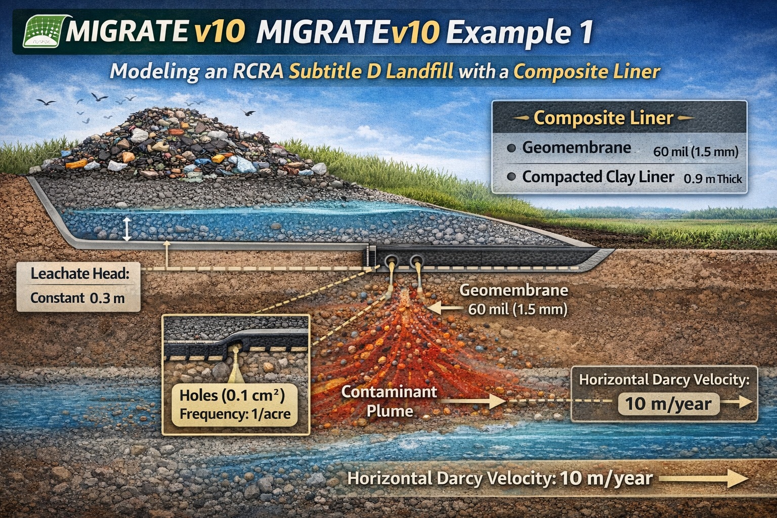
MIGRATEv10 Example 1 demonstrates how to model contaminant migration from a U.S. RCRA Subtitle D landfill using a composite liner system and a primary leachate collection system (PLCS). This example is foundational for understanding how engineered barriers control leakage and how contaminants move into underlying groundwater systems.
The simulation focuses on a volatile organic compound (VOC) with a constant source concentration and evaluates how leakage through defects in the geomembrane contributes to groundwater contamination.
Conceptual Model Overview
The modeled landfill system includes:
- A composite liner system:
- 60 mil (1.5 mm) HDPE geomembrane
- 0.9 m thick compacted clay liner
- A primary leachate collection system
- An underlying aquifer with horizontal groundwater flow
Key Modeling Objective
The purpose of this example is to:
- Estimate leakage through geomembrane defects
- Simulate contaminant transport into the aquifer
- Demonstrate how MIGRATEv10 applies established analytical methods for liner performance
Composite Liner System Details
1. Geomembrane Properties
| Property | Value |
|---|---|
| Thickness | 60 mil (1.5 mm) |
| Condition | Good contact with clay liner |
Defect Assumptions
- Hole area: 0.1 cm²
- Frequency: 1 hole per acre (2.5 per hectare)
These defects represent realistic imperfections that control leakage rates.
2. Compacted Clay Liner
| Property | Value |
| Thickness | 0.9 m |
The clay liner acts as a secondary barrier, reducing flow that passes through geomembrane defects.
Leakage Calculation Method
Leakage through the composite liner is calculated automatically in MIGRATEv10 using:
- Giroud et al. (1992)
- Giroud and Bonaparte (1989)
These methods account for:
- Hole size and frequency
- Hydraulic head
- Interface contact conditions
This provides a realistic estimate of leakage rates without requiring manual calculations.
Landfill Geometry and Source Conditions
| Parameter | Value |
| Landfill Length | 200 m |
| Landfill Width | 200 m |
| Leachate Head | 0.3 m |
| Source Concentration | 1500 μg/L (constant) |
The constant concentration assumption simplifies the model while representing a sustained contaminant source.
Aquifer Properties
| Parameter | Value |
| Flow Direction | Parallel to landfill length |
| Darcy Velocity | 10 m/year |
The aquifer flow controls the down-gradient transport of contaminants once they enter groundwater.
Modeling Approach in MIGRATEv10
Step 1: Define Landfill Geometry
- Input landfill dimensions (200 m × 200 m)
- Specify liner system configuration
Step 2: Configure Composite Liner
- Enter geomembrane thickness and defect characteristics
- Define clay liner thickness and properties
Step 3: Apply Leakage Model
- Use built-in Giroud method (automatic in MIGRATE-GUI)
Step 4: Define Source Term
- Set constant concentration: 1500 μg/L
- Apply constant leachate head: 0.3 m
Step 5: Configure Aquifer Flow
- Set horizontal Darcy velocity: 10 m/year
- Define down-gradient boundary conditions
Step 6: Run Simulation
- Evaluate contaminant migration into the aquifer
- Analyze plume development over time
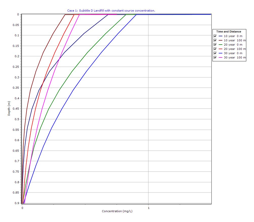
Graphical Output: Depth vs Concentration
PDF Report
 Loading…
Interpretation of Results
1. Leakage Through Defects
Even small geomembrane holes can result in measurable leakage, especially under sustained hydraulic head.
2. Role of Composite Liner
The combination of geomembrane + clay liner significantly reduces contaminant flux compared to single-layer systems.
3. Groundwater Transport
Once contaminants enter the aquifer:
- They migrate in the direction of groundwater flow
- Plume shape and extent depend on Darcy velocity
4. Long-Term Behavior
With a constant source, contaminant concentrations may:
- Increase over time
- Reach steady-state conditions depending on system parameters
Key Takeaways
- Composite liners are highly effective but not impermeable
- Small defects can control overall leakage rates
- MIGRATEv10 simplifies complex calculations using established methods
- Aquifer flow conditions are critical for predicting plume migration
- This example provides a strong foundation for landfill impact assessments
Final Thoughts
MIGRATEv10 Example 1 is an essential starting point for modeling landfill systems under RCRA Subtitle D regulations. It demonstrates how engineering design, material properties, and hydrogeologic conditions interact to control contaminant migration.
For real-world applications, additional considerations may include:
- Variable source concentrations
- Degradation of liner materials
- Heterogeneous subsurface conditions
As always, modeling results should be interpreted with engineering judgment and site-specific data.
Learn more about our Contaminant Transport Modeling Solutions
MIGRATE Examples
- MIGRATEv10 Example 2: Composite Liner System with Primary & Secondary Leachate Collection
- MIGRATEv10 Example 3: Pure Diffusion of a Conservative Contaminant
- MIGRATEv10 Example 4: Finite Mass Source and Aquifer Mixing with Base Outflow
- MIGRATEv10 Example 5: Understanding Integration, Accuracy, and the Role of Engineering Judgment
- MIGRATEv10 Example 6: Eliminating Negative Concentrations Through Improved Integration
- MIGRATEv10 Example 7: Improving Accuracy with User-Selected Fourier Integration
- MIGRATEv10 Example 8: Evaluating Contaminant Migration at Multiple Lateral Positions
- MIGRATEv10 Example 9: Comparison with the TDAST Analytical Solution
- MIGRATEv10 Example 10: Contaminant Transport in Fractured Media with Sorption
- MIGRATEv10 Example 11: Contaminant Migration from Two Adjacent Landfill Cells
- MIGRATEv10 Example 12: Modeling Time-Dependent Source Histories for Multiple Landfill Cells
- MIGRATEv10 Example 13: Termination of Primary Leachate Collection System
Comparison between POLLUTE and MIGRATE
- MIGRATEv10 vs POLLUTEv10: Pure Diffusion Comparison
- MIGRATEv10 vs POLLUTEv10: Advective–Diffusive Transport Comparison
- MIGRATEv10 vs POLLUTEv10: Finite Mass Source Comparison
- MIGRATEv10 vs POLLUTEv10: Hydraulic Trap (Finite Mass Source) Comparison
- MIGRATEv10 vs POLLUTEv10: Fractured Layer with Sorption Comparison