
Introduction
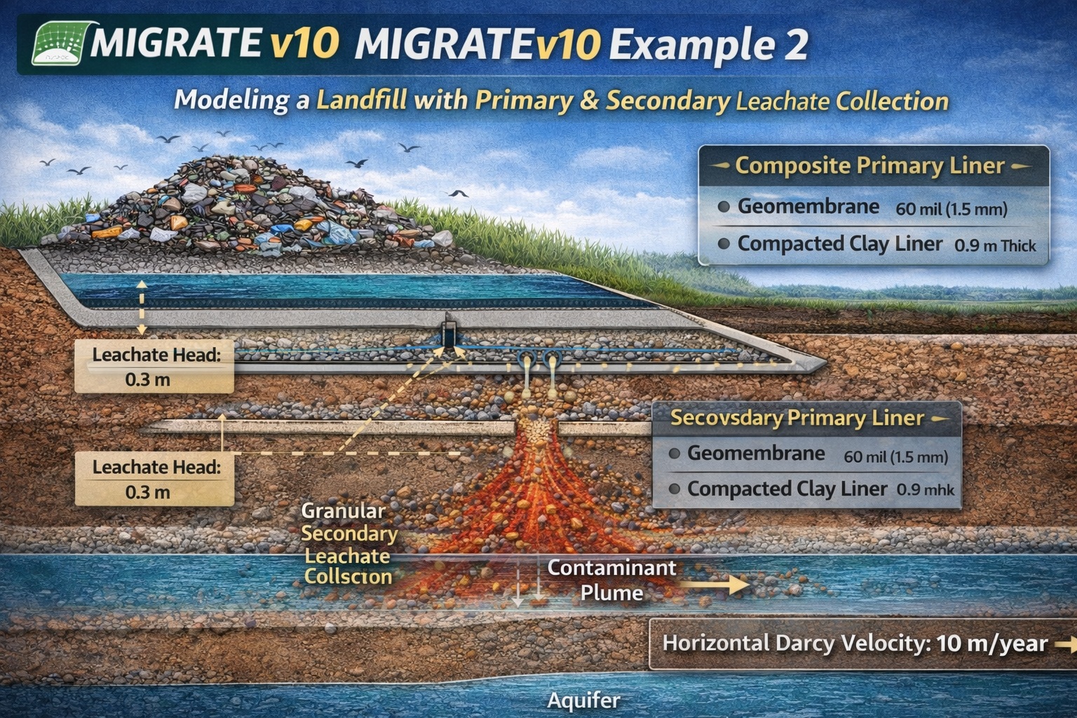
MIGRATEv10 Example 2 builds on the fundamentals introduced in Example 1 by incorporating a more advanced landfill design that includes:
- A composite primary liner
- Primary and secondary leachate collection systems
- A compacted clay secondary liner
- An underlying aquitard and aquifer system
This example demonstrates how multiple engineered barriers work together to minimize contaminant migration and how MIGRATEv10 models leakage and transport through a layered system.
Conceptual Model Overview
The modeled landfill system includes:
- Composite primary liner (geomembrane + compacted clay)
- Primary leachate collection system (PLCS)
- Secondary leachate collection system (SLCS)
- Compacted clay secondary liner
- Aquitard (low permeability layer)
- Underlying aquifer
This multi-barrier design is typical of modern landfill engineering practices.
Key Modeling Objective
The goal of this example is to:
- Simulate leakage through a composite liner with defects
- Evaluate the effectiveness of secondary containment systems
- Model contaminant transport through multiple subsurface layers
Composite Primary Liner Details
Geomembrane
| Property | Value |
|---|---|
| Thickness | 60 mil (1.5 mm) |
| Condition | Good contact with clay liner |
Defect Characteristics
- Hole area: 0.1 cm²
- Frequency: 2.5 per hectare (1 per acre)
These defects control the leakage rate through the geomembrane.
Compacted Clay Primary Liner
| Property | Value |
| Thickness | 0.9 m |
The clay liner provides additional resistance to flow, forming a composite barrier with the geomembrane.
Secondary Containment System
Secondary Leachate Collection System (SLCS)
| Property | Value |
| Thickness | 0.3 m |
| Material | Granular drainage layer |
This layer collects leakage that passes through the primary liner.
Secondary Clay Liner
| Property | Value |
| Thickness | 0.9 m |
Acts as a final barrier before contaminants can reach natural subsurface layers.
Subsurface Hydrogeology
Aquitard
| Property | Value |
| Thickness | 3 m |
A low-permeability layer that further restricts contaminant movement.
Aquifer
| Property | Value |
| Thickness | 3 m |
| Darcy Velocity | 10 m/year |
The aquifer represents the receptor system, where contaminants may migrate if containment fails.
Source and Hydraulic Conditions
| Parameter | Value |
| Source Concentration | 1500 μg/L |
| Leachate Head (Primary Liner) | 0.3 m |
| Leachate Head (Secondary Liner) | 0.3 m |
| Groundwater Level | At top of aquitard (3 m) |
| Landfill Width | 200 m |
The constant concentration assumption represents a sustained contaminant source.
Leakage Modeling Approach
Leakage through the composite primary liner is calculated automatically in MIGRATEv10 using:
- Giroud et al. (1992) methodology
This approach accounts for:
- Geomembrane defects
- Hydraulic head
- Interface conditions
No manual calculation is required, as MIGRATE-GUI performs this internally.
Modeling Workflow in MIGRATEv10
Step 1: Define Geometry
- Input all layers:
- Primary liner system
- Secondary system
- Aquitard and aquifer
Step 2: Configure Composite Liner
- Enter geomembrane properties and defect parameters
- Define clay liner thickness
Step 3: Add Secondary System
- Include granular SLCS
- Define secondary clay liner
Step 4: Apply Hydraulic Conditions
- Set leachate heads (0.3 m for both liners)
- Define groundwater level and aquifer flow
Step 5: Define Source
- Constant concentration: 1500 μg/L
Step 6: Run Simulation
- Evaluate leakage and contaminant transport
- Analyze plume development in the aquifer
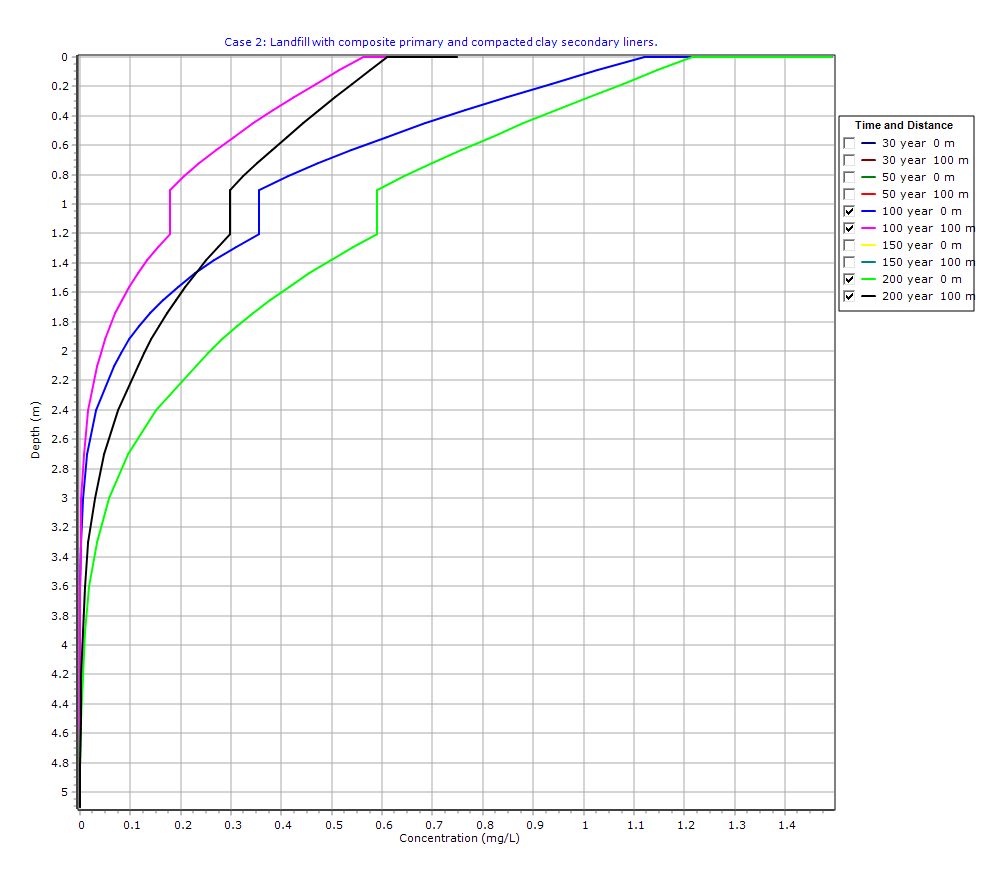
Graphical Output: Depth vs Concentration
PDF Report
 Loading…
Interpretation of Results
1. Effectiveness of Double Liner System
The addition of a secondary liner significantly reduces the risk of contaminant migration.
2. Role of SLCS
The secondary leachate collection system intercepts leakage, reducing load on the secondary liner.
3. Importance of Aquitard
The aquitard provides an additional natural barrier, slowing contaminant movement.
4. Groundwater Impact
If contaminants reach the aquifer, transport is governed by:
- Darcy velocity
- Layer properties
- Source persistence
Key Takeaways
- Double liner systems provide redundant protection against leakage
- Geomembrane defects remain the primary pathway for leakage
- MIGRATEv10 simplifies complex leakage calculations
- Secondary systems are critical for risk mitigation
- Aquitards enhance long-term environmental protection
Final Thoughts
MIGRATEv10 Example 2 demonstrates a more realistic landfill design by incorporating multiple engineered and natural barriers. This layered approach reflects modern regulatory expectations and highlights how different components interact to control contaminant migration.
For real-world applications, additional considerations include:
- Long-term degradation of materials
- Variable leachate generation rates
- Site-specific hydrogeology
As always, modeling should be supported by field data and professional judgment.
Learn more about our Contaminant Transport Modeling Solutions
MIGRATE Examples
- MIGRATEv10 Example 1: Modeling a RCRA Subtitle D Landfill with a Composite Liner
- MIGRATEv10 Example 3: Pure Diffusion of a Conservative Contaminant
- MIGRATEv10 Example 4: Finite Mass Source and Aquifer Mixing with Base Outflow
- MIGRATEv10 Example 5: Understanding Integration, Accuracy, and the Role of Engineering Judgment
- MIGRATEv10 Example 6: Eliminating Negative Concentrations Through Improved Integration
- MIGRATEv10 Example 7: Improving Accuracy with User-Selected Fourier Integration
- MIGRATEv10 Example 8: Evaluating Contaminant Migration at Multiple Lateral Positions
- MIGRATEv10 Example 9: Comparison with the TDAST Analytical Solution
- MIGRATEv10 Example 10: Contaminant Transport in Fractured Media with Sorption
- MIGRATEv10 Example 11: Contaminant Migration from Two Adjacent Landfill Cells
- MIGRATEv10 Example 12: Modeling Time-Dependent Source Histories for Multiple Landfill Cells
- MIGRATEv10 Example 13: Termination of Primary Leachate Collection System
Comparison between POLLUTE and MIGRATE
- MIGRATEv10 vs POLLUTEv10: Pure Diffusion Comparison
- MIGRATEv10 vs POLLUTEv10: Advective–Diffusive Transport Comparison
- MIGRATEv10 vs POLLUTEv10: Finite Mass Source Comparison
- MIGRATEv10 vs POLLUTEv10: Hydraulic Trap (Finite Mass Source) Comparison
- MIGRATEv10 vs POLLUTEv10: Fractured Layer with Sorption Comparison