
GaeaSynergy Buildings and Structures

See Site Infrastructure Together with the Subsurface

Define simplified buildings, tanks, silos, piles, shafts and excavations in 2D, then display them with project data in the GaeaSynergy 3D environment.

Add the surface and below-ground context needed to understand spatial relationships and communicate project conditions.
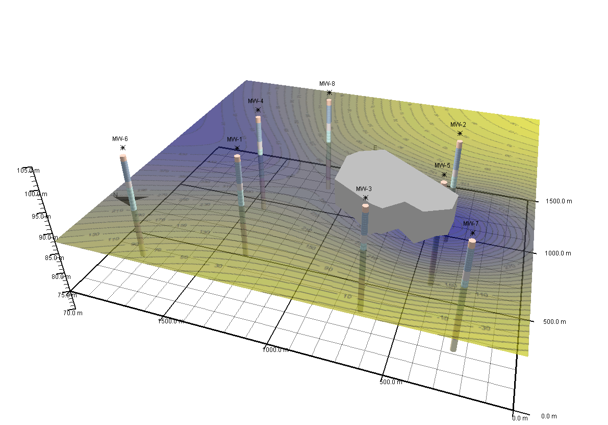
Three-dimensional GaeaSynergy environmental data visualization showing site structures, monitoring locations and subsurface information in spatial context
3D Environmental Data Visualization—site structures and environmental information presented together in a recognizable spatial context.

Give Technical Data a Recognizable Site Context

Buildings and structures act as spatial reference objects. Their footprints, elevations and dimensions help users understand where boreholes, cross-sections, contour surfaces and other project information sit in relation to the developed site.

  • Represent existing or proposed site features with simplified geometry
  • Position features using local or map coordinates
  • Place objects above or below ground using base or top elevation
  • Combine structures with the project GIS overlay
  • Display structures with subsurface information in 3D
Appropriate scope: These tools support conceptual site and subsurface visualization. They are not a replacement for detailed CAD, BIM, architectural or structural-design software.

Seven Supported Structure Types

Select a purpose-built object type, then define its geometry and location within the building/structure view.

Rectangular Buildings

Create straightforward building volumes with a rectangular plan footprint.

Irregular Buildings

Define a custom building outline by selecting the footprint vertices in the 2D view.

Storage Silos

Represent vertical storage features within industrial and resource project sites.

Storage Piles

Show stockpiles or other raised storage features with controlled height and side slope.

Shafts

Place vertical shaft features in relation to geological and project information.

Excavations

Define a custom excavation footprint and position it by elevation and depth.

Storage Tanks

Represent tank locations above or below ground for environmental and industrial context.

Control Position, Dimensions and Orientation

Each structure has geometry settings for placing it accurately within the project’s local and mapped coordinate systems.

  • Specify either the base elevation or top elevation
  • Set vertical height
  • Define side-slope angle
  • Set tilt direction and tilt angle
  • Enter local easting and northing
  • Enter map easting and northing
  • Control available east and north extents

For irregular buildings, shafts and excavations, relevant extents are derived from their defined footprint rather than edited as simple rectangular dimensions.

Efficient 2D Layout and Editing

Create the site arrangement in a building/structure view before using the objects in 3D.

Move and Resize

Adjust a selected object with the mouse or enter its size and position through its properties.

Scale and Rotate

Scale or rotate selected structures using the available editing commands.

Lock the Layout

Lock object size and position to prevent unintended changes after placement.

Cut, Copy and Paste

Reuse selected objects when a project contains repeated buildings or structures.

Multiple Selection

Draw a selection box around several objects to edit them as a group.

Align Structures

Use alignment commands to organize multiple selected objects consistently.

From a 2D Footprint to an Integrated 3D View

A structured setup sequence keeps horizontal placement, vertical placement and project context consistent.

1

Create the Structure View

Define the view’s extents, grid interval and unique project name.

2

Add the Site Objects

Select each structure type and place its center or define its irregular footprint vertices.

3

Set Geometry

Enter elevation, height, slope, tilt, position and the available dimensions.

4

Organize the Layout

Move, resize, rotate and align objects, then lock stable elements.

5

Review GIS Context

Turn the project GIS overlay and individual objects on or off to verify placement.

6

Add to 3D and Project Views

Display the structures with project data in 3D, then include that 3D display in a printable project view.

Applications Across Project Types

Add enough site detail to communicate the relationship between infrastructure and interpreted subsurface conditions.

Environmental Sites

Show tanks, excavations and buildings relative to sampling locations, wells and interpreted contamination.

Geotechnical Investigations

Place proposed or existing building footprints and excavations over boreholes and geological surfaces.

Industrial Facilities

Represent buildings, tanks, silos and storage piles within a coordinated site model.

Mining and Resources

Display shafts, piles and site buildings with boreholes, sections and interpreted surfaces.

Excavation Planning

Visualize excavation geometry in relation to site elevation and subsurface interpretations.

Project Communication

Create recognizable 3D context for internal review, client discussions and project-view figures.

Connect Structures to the Rest of the Project

The strongest value comes from displaying simplified site objects with the technical data already managed in GaeaSynergy.

Connected capabilityHow structures add contextRelated page
Geographic Information SystemUse mapped coordinates and the project GIS overlay to confirm horizontal placement.Explore GIS
Boreholes and wellsShow investigation locations around or beneath buildings, tanks and excavation footprints.Explore WinLoG
Cross-sectionsRelate vertical geological interpretations to recognizable surface and below-ground features.Explore WinFence
Grids and contour mapsDisplay structures with topographic, groundwater, stratigraphic or property surfaces.Explore gridding
3D display and project viewsCombine the complete context in 3D and place the resulting display in printable project output.Explore 3D display
Output note: A building/structure view is not printed directly. Add the structures to a 3D view and include that 3D view in a project view for printed output.

Buildings and Structures Resources

Use the product overview for capability planning and the manual for current creation and editing procedures.

3D Structures Overview

See how above-ground and below-ground site objects add context to GaeaSynergy visualization.

Read the Knowledge Center guide

Structure Types Manual

Review the supported building, structure and excavation types and access their detailed procedures.

Open the structures manual

Quick-Start Workflow

Follow the current steps for creating a view, placing objects, editing them and using them in 3D.

Open the quick-start guide

Add Site Context to Your Subsurface Model

Create simplified structures, position them accurately and display them with the project’s boreholes, sections, surfaces and GIS information.