
Integrated Project · 3D Visualization
Integrated 3D Geological Project Model
Aerial imagery, borehole information, interpreted strata and intersecting sections combined in one spatial project view.
3D modelBoreholesGIS context



Explore how GaeaSynergy connects project data, GIS context, calculated surfaces, subsurface interpretations, dashboards and technical deliverables.
The examples on this page focus on the integrated platform. Product-specific logs, cross-sections, environmental views and laboratory reports remain available in their dedicated libraries.
This presentation sheet shows the value of the platform: several project outputs remain connected to the same investigation context instead of being assembled as unrelated files.
Use these capability pages to understand how each function contributes to the integrated examples.
Organize project records and connect information used by maps, models, dashboards and reports.
Explore data managementMonitor project status and present borehole, sample, laboratory and test information.
Explore platform dashboardsManage locations, layers, aerial context, project boundaries and mapped results.
Explore GISCalculate surfaces from project observations and present spatial trends as contours.
Explore griddingAdd simplified site objects to provide engineering and geographic context.
Explore structuresCombine boreholes, sections, surfaces, geological solids and GIS information.
Explore 3D displayExchange supported project, investigation and GIS information with external workflows.
Explore import and exportCoordinate users and concurrent licenses across the shared project environment.
Explore user managementFilter the collection by capability, then open any image at full size or follow its technical feature link.
Showing all 8 examples
Aerial imagery, borehole information, interpreted strata and intersecting sections combined in one spatial project view.

Multiple boreholes and connected section planes present interpreted strata across the investigation area.

A calculated contour surface is displayed with boreholes and intersecting sections to clarify spatial relationships.

A coordinated deliverable combining a project map, 3D model, contour map, cross-section and borehole log.

A project boundary is positioned over aerial imagery to retain property, roadway and neighbouring-land context.

A georeferenced investigation area is displayed with an aerial basemap and surrounding urban infrastructure.

A project contour surface is overlaid on aerial imagery so calculated spatial trends remain connected to the site.
GaeaSynergy provides the shared project context. Use each dedicated library for the full collection of product-specific outputs.
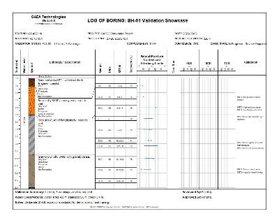
Borehole, well, core and specialized log examples with templates, XML data and validation reports.
Open WinLoG Library
Geological cross-sections and 3D fence diagrams for environmental, geotechnical and geological projects.
Open WinFence Library
Environmental project, sample, well, laboratory-result and reporting examples.
Open EDMS Library
Laboratory test reports for asphalt, concrete, rock, soil and aggregate workflows.
Open GDMS LibraryUse a real multidisciplinary project to confirm the connections that matter to your organization.
Choose representative borehole, laboratory, environmental, GIS and document information.
Confirm the applicable import, export and migration paths for existing data.
Create the maps, surfaces, sections, dashboards and reports needed by the project team.
Evaluate data coverage, licensing, user roles, workflows and final deliverables.
Evaluate GaeaSynergy with representative data and compare the integrated workflow with your current collection of disconnected tools.

GAEA Technologies develops and distributes geoscience and engineering solutions worldwide. Our solutions have been used for over 30 years by companies and organizations around the world.
© 2026 GAEA Technologies. All Rights Reserved.